GENERAL
It is recommended that servicing of this
receiver be done
by the
factory
service
center. Special equipment and skills are
maintained at the
factory
to give
fast
and
efficient service on
all
of our
products.
When
retuming radio
receivers
to the
factory
for
service,
include
crystals,
ac
and dc power
cables
and telescoping
antenna.
Disconnect cables
and
antenna, pack carefully and
include a trrief. detailed description of the difficulty
you
are
having.
The receiver circuitry is designed to
utilize
the best
feafures
of
four
types of semiconductors:
rectifier diodes,
conventional
bi-polar
transistors, insulated-gate field-effect
transistors
and
integrated circuits. Servicing
should
not be
attempted by anyone
who
is not familiar
with the
manu-
facturer's recommendations and
cautions
relating to
each
of
these
devices. The
use of
ohmmeters
is particularly hazardous
since they
can deliver voltages and currents
large enough
to
damage semicon duc tors.
Unusual
circuitry
in
this
receiver
includes
the automatic
tuning
system.
I.C.
No.1 and
the
associated
circuits
generate
tuning
voltages to
track the
antenna, r-f and oscillator
circuits
as
channels are scanned.
Also, when the receiver is operating
in the
"L"
band,
loading coil L-l
is
switched
into the
telescop-
ing
antenna
circuit.
Audio output power
is
measured
with
bursls of modula-
tion
or by measuring
the
maxirnum excursion on
voice
modulation as
shorn
on an oscilloscope.
S'hen
a
continuous
tone
is received. the output
rrill
start
at
full porver
and then
decrease to approximatel,v
half power
to
protect
the output
inteEated circuit from
overload.
It rrill
then
retum
to
full
power
for
voice communications.
The LED indicators have
a
forward
voltage drop
of
about
l.6v at 20ma.
The current
should
not
exceed 50ma. They
are
polarized
and
may
be damaged by
a
high reverse voltage.
When
a
channel lamp
does not light,
the
failure
may
be either
the
lamp
or the switching
I.C. If
the
channel n'orks, check
the
lampi if not, check
the
I.C. [hen
groups
of
lamps are out.
refer
to the
losic chart.
TRACKED TUNING
SYSTEM
All tuned
circuits
in
the
RF sections
are tuned
by voltage-
variable
capacitators which
optimize the
radio
for each
crystal
individually
regardless of
where
it
falls
in any
band. This tun-
ing is
done automatically
and
allows the
Bearcat
IV to tune
all
parts of
any
band without
compromise.
Tracked
tuning is accomplished
by
means of a
DC
voltage
applied
to
YVCI
.
2.3,4,5.6.
This
voltage
varies
with
crystal
frequencv
and
is
higher
for higher
frequency
crystals.
It is ad-
justed
br Tl.
T2.
Rl7 and
R52.
Facton-
alignment
of the
RF and
tracked
tuning
system
in-
volves
highlv specialized
equipment
and
training
not
available
to
nornral
senice
activities.
Because
this
unique
feature is out-side
the
experience of
eren the
most highlr- trained
technicians.
these
adjustments
should
onlv
be
made bv
Electra.
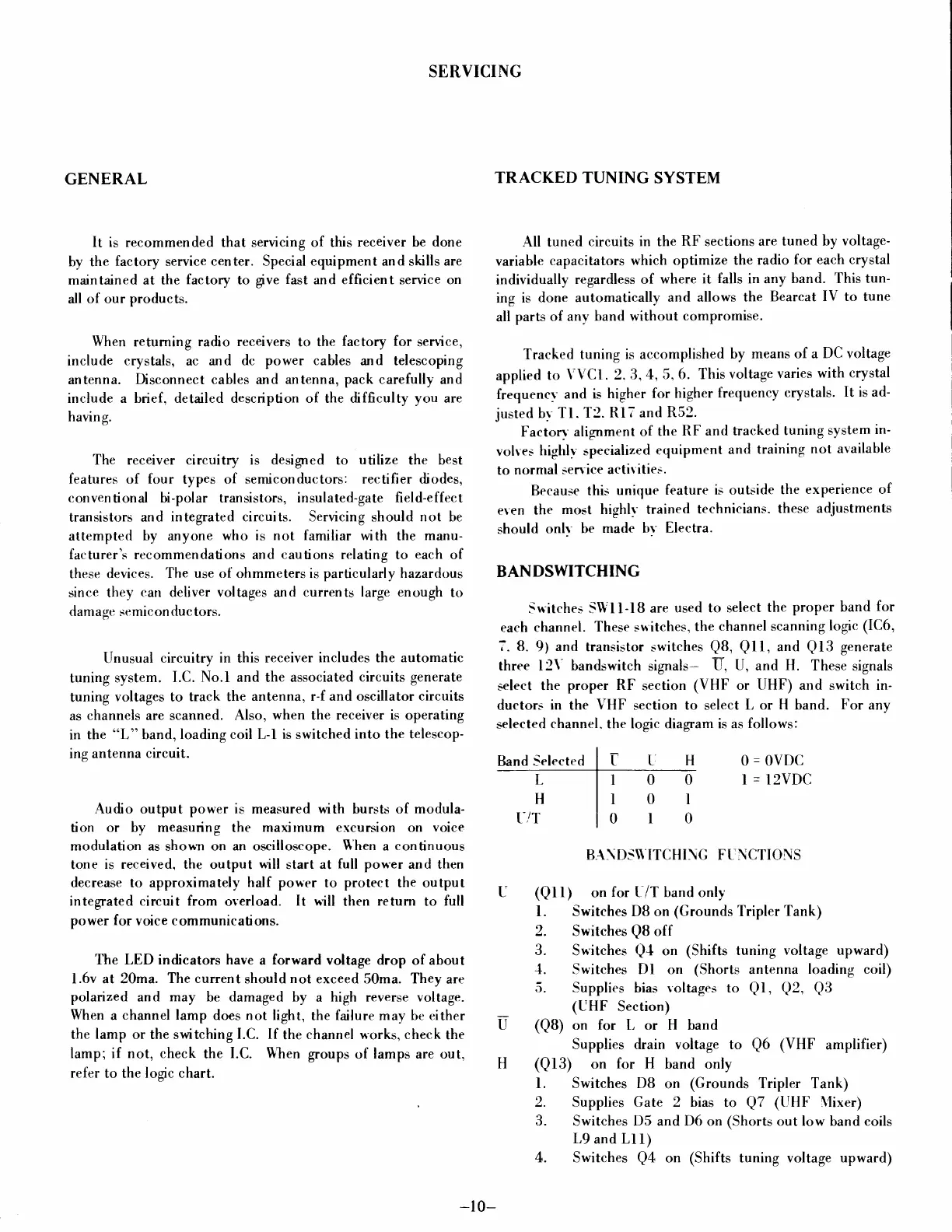
BANDSWITCHING
Switches SWll-lB
are
used to select
the
proper
band
for
each channel.
These sn'itches,
the
channel scanning
logic (IC6,
7.8.9) and
hansistor
switches
QB,
Qll,
and
Q13
generate
three l2\' bandswitch
signals-
U, U,
and
H.
These
signals
select
the
proper RF
section
(VHF or
UHF)
and switch in-
ductors
in
the
VHF
section
to select
L or H band.
For
any
selected
channel. the logic diagram is as
follows:
Band Selected
0
=
OVDC
I
=
12VDCL
H
t-/T
BA\DS\\'ITCHI\G FUNCTIONS
(Qtt)
on
for
L/T band only
l. Switches DB on
(Grounds
Tripler Tank)
2. Switches
QB
off
3.
Switches
Q{
on (Shifts
tuning voltage upward)
{. Switches Dl on
(Shorts
antenna
loading coil)
5.
-supplies bias roltages to
Ql, Q2, Q3
(UHF Section)
(QB)
on
for
[,
or
H band
Supplies drain voltage to
Q6
(VHF
amplifier)
(Ql3) on
for
H band only
l. Switches DB
on
(Grounds
Tripler Tank)
2.
Supplies
Gate 2 bias
to
Q7
(UHF \lixer)
3.
Switches D5 and D6 on
(Shorts
out low
band
coils
L9
and Ll
l)
4. Switches
Q4
on (Shifts tuning voltage
upward)
SERVICING
I
I
0
0
I
0
0
0
I
U
-10-
 Loading...