CRYSTAT
INSTALLATION
DISCONNECT
POWER BEFORE
REMOVING
CABINET
LEAVE POWER
OFF
WHILE
INSTALLING
CRYSTALS
To
remove
the
cabinet, first
remove
the screw at the bot-
tom rear
edge.
Push
the
rear panel forward
through
the
cab-
inet. The components
and
crystal
sockets are in
full
view
and
easily
accessible.
Up
to
eight crystals may
be
installed
in any combination
of
L, H,
or
U/T
bands. Each crystal is installed
in the sockets
corresponding to its channel.
(Channel I is nearest
the side
of
the
radio)
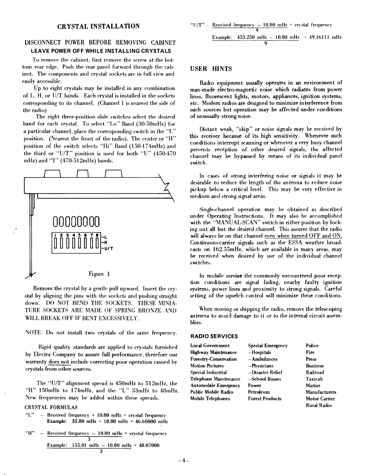
The
eight
three-position
slide
switches select the desired
band for each
crystal.
To
select
"Lo"
Band
(30-50mHz)
for
a particular channel,
place
the corresponding
switch
in the
"L"
position.
(Nearest the
front
of the radio).
The
center
or
"H"
position
of the
switch selects
"Hi"
Band (150-l74mHz) and
the third or
o'U/T"
position
is
used for
both
"U"
(450-470
mHz)
andooT"
(470-5l2mHz)
bands.
Remove
the
crystal by a
gentle
pull
upward.
Insert
the cry-
stal
by
aligning the pins with
the
sockets and pushing
straight
down. DO NOT BEND
THE SOCKETS.
THESE \'IINIA-
TURE
SOCKETS
ARE N,IADE
OF SPRING
BRONZE
AND
WILL
BREAK OFF
IF
BENT
EXCESSIVELY.
NOTE: Do not
install
two crystals
of the
same
frequency.
Rigid
qualiry'
standards are applied to crystals furnished
by Electra Company
to assure full performance.
therefore our
warranty does
not include
correcting
poor operation caused
by
crystals
from
other
sources.
The
"U/T"
alignment
spread is 450mHz
to ll2mH.z,
the
"H"
150mHz to
l7[mHz,
and the
"L"
33m[z
to ABmHz.
New
frequencies
may be
added within
these
spreads.
CRYSTAL FORMULAS
'(L'r
Received
frequency
+
10.80
mHz
=
crystal frequency
Example:
35.80
mHz
+
f0.80 mHz
=
46.600fi) mHz
"H"
-
Received frequency
-
10.80 mHz
=
crystal
frequency
3
Example:
155.01 mHz
-
10.80 mHz
=
48.07000
3
,,UIT"
Received
frequency
-
10.80 mHz
=
cr1 stal
frequency
I
Example: 453.250
mHz
-
10.80 mHz
=
{9.16llI
mHz
9
USER
HINTS
Radio
equipment
usually
operates
in an
environment
of
man-made
electro-magnetic
noise which
radiates from power
lines, fluorescent
lights, motors, appliances,
ignition systems,
etc.
Modern radios
are
designed
to minimize
interference
from
such
sources
but
operation
may be affected
under conditions
of
unusually
strong
noise.
Distant
weak,
".hp"
or
noise
signals
may be
received by
this
receiver because of
its
high
sensitiuity.
Whenever
such
conditions
interrupt
scanning
or
whenever a
very
busy
channel
prevents
reception
of other
desired signals, the
affected
channel
may
be bypassed
by
means
of
its individual
panel
switch.
ln cases of strong
interfering noise
or signals
it may be
desirable to
reduce
the
length of the antenna to
reduce
noise
pickup
below a
critical level.
This
may be very
effective
in
medium
and
strong signal
areas.
-Single-channel operation
may
be obtained as
described
under Operating
Instructions. It may
also
be
accomplished
with
the
"\IANUAL-SCAN"
switch
in either
position
by
lock-
ing
out
all but
the
desired channel. This assures that the
radio
will
alwavs be
on that channel
even when
turned
OFF and ON.
Continuous-carrier
signals
such
as
the
ESSA weather broad-
casls on 162.55mH2, which are available in many areas,
may
be received when desired by use of
the
individual channel
swi
tches.
In mobile
service the
commonly encountered
poor recep-
tion conditions
are signal
fading, nearhy faulty ignition
systems,
power
lines
and
proximity
to strong signals.
Careful
setting of the
squelch
control
will minimize these conditions.
Shen
moring
or shipping
the radio, remove
the
telescoping
antenna to avoid damage
to
it or to the internal circuit assem-
blies.
RADIO
SERVICES
Locd Govemment
Specid
Emergency Police
Highway Maintenance
-Hospitds
Fire
Forestry-Conserration
-Ambulances
Press
Motion
Pictures
-Physicians
Business
Special
Indusbial
-Disaster
Relief
Railroad
Telephone Maintenance
-School
Busses Taxicab
Automotile Emergency Power
Marine
Public
Mobile
Radio
Peholeum
Manufachrers
Mobile Telephones Forest Products
Motor
Carrier
Rural Radio
00 0000 00
t23.1
5878
[il[[[[00
-4-
 Loading...