Do you have a question about the Electro-Voice 603TR and is the answer not in the manual?
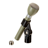
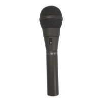
Details the Model 603TR as a hand-held dynamic microphone for high articulation speech in noisy environments.
Highlights its transistorized design, dual sound entrances for noise rejection, and adjustable output.
Specifies the microphone type as transistorized dynamic with a frequency response of 200 to 4,000 Hz.
Details impedance matching for carbon inputs and a differential close-talking polar pattern.
Defines adjustable output level and the Acoustalloy diaphragm material.
Covers case material, finish, amplifier gain, current drain, supply voltage, and max output.
Lists dimensions, net weight, connector type, and cable specifications.
Specifies temperature range and FAA approval.
Procedure for disassembling the microphone, including head removal and cleaning methods.
Guidelines for inspecting parts, checking connections, and replacing damaged components.
Instructions for reassembly, switch operation checks, and output level testing.
Illustrates the wiring for a 3-wire connection using a PJ-068 plug.
Illustrates the wiring for a 4-wire connection using an XLR-4-12C connector.
Diagram showing the test setup for a 3-wire configuration.
Diagram showing the test setup for a 4-wire configuration.
Diagrams showing the back of the microphone case for 3-wire and 4-wire connections.
Diagram showing the front of the microphone case with internal components.
Exploded view of the Model 603TR showing all components for assembly.
Lists part numbers, quantities, and nomenclature for all replaceable components.
| Brand | Electro-Voice |
|---|---|
| Model | 603TR |
| Category | Microphone |
| Language | English |