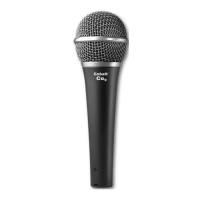
Do you have a question about the Electro-Voice Cobalt Co9 and is the answer not in the manual?
Position microphone zero to six inches from windscreen, on axis for optimal vocal performance.
Position microphone five to ten inches from windscreen, on axis for optimal spoken word performance.
Guidelines for aiming, proximity, multi-mic spacing, handling noise, and bass tone.
Details on the dynamic element, neodymium magnet structure, and 50 Hz to 18 kHz frequency range.
Specifies the cardioid polar pattern and low-Z balanced impedance (600 Ohms).
Provides sensitivity rating (3.2 mV/PA) and 3-pin XLR microphone connector details.
Lists length, diameter, shank, net weight, and shipping weight of the microphone.
Notes that a stand adapter and gig bag are included with the microphone.
Illustrates the microphone's directional sensitivity at different angles and frequencies.
Shows the typical frequency response curve, indicating sensitivity across different frequencies.
| Brand | Electro-Voice |
|---|---|
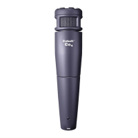
| Model | Cobalt Co9 |
| Category | Microphone |
| Language | English |