Do you have a question about the Electro-Voice PA2400T and is the answer not in the manual?
General precautions for safe operation, installation, and maintenance of the appliance.
Guidelines for proper disposal of electrical equipment according to WEEE regulations.
Instructions for qualified personnel, emphasizing safety regulations and component replacement.
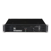
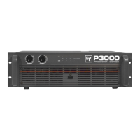
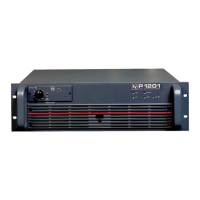
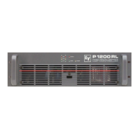
Overview of ElectroVoice PA-Series power amplifiers, highlighting performance, reliability, and features.
Instructions for unpacking the amplifier and details about the warranty period and certificate.
Guidelines for proper installation, ventilation, and environmental temperature limits for safe operation.
How to use the mains switch and the function of the power indicator LED.
Explanation of the Protect and Limit LEDs, indicating system status and potential issues.
Displays the amplifier's current modulation level, indicating signal strength.
Details balanced inputs for signal sources and controls for setting amplification levels.
Options to select operating modes like Dual, Parallel, or Bridged for amplifier channels.
Attenuates low bass audio signals with selectable cut-off frequencies.
Details connections for low impedance and floating (50V, 70V, 100V) outputs, including polarity and impedance.
Instructions for connecting loads in Bridged Mode, emphasizing minimal impedance and input signal.
Example configuration for PA2400T with 100V speaker systems connected.
Information on mains fuse, socket, and how to select the correct mains voltage.
Recommendations for balanced/unbalanced cables and wiring examples for audio inputs.
Table detailing mains voltage, current, power, and dissipation for PA2450L.
Table detailing mains voltage, current, power, and dissipation for PA4150L.
Details mains voltage, current, power, and dissipation for PA2400T (100V output).
Details mains voltage, current, power, and dissipation for PA2250T (100V output).
Details mains voltage, current, power, and dissipation for PA1250T (100V output).
Specifications for maximum and rated output power across different load impedances and models.
Technical details on voltage gain, slew rate, and input sensitivity for various models.
Specifies frequency response, power bandwidth, and input impedance.
Details damping factor, signal-to-noise ratio, and power requirements.
Lists protection mechanisms, cooling, dimensions, and weight of the amplifiers.
Block diagram illustrating signal path, filters, limiters, and power amp stages for channels A/B.
Shows protection circuits, thermal sensing, relay drive, and power supply components.
Block diagram detailing the signal path, filters, limiters, and power amplifier stages for channels C and D.
Illustrates protection circuits, thermal and current sensing, and fan control mechanisms.
Block diagram showing the signal flow, including input stages, filters, protection, and power amplifier sections.
Details the power supply, transformer, voltage selector, and control circuits for the amplifiers.
Block diagram illustrating the signal path, filters, limiters, and power amplifier for the PA1250T model.
Shows the power supply, transformer, voltage selector, and control circuitry integrated into the PA1250T.
Diagram showing the physical dimensions (W x H x D) of the PA series amplifiers in millimeters.
| Brand | Electro-Voice |
|---|---|
| Model | PA2400T |
| Category | Amplifier |
| Language | English |