Do you have a question about the Electro-Voice P900RL and is the answer not in the manual?
Instructions for qualified personnel on servicing to reduce electric shock risk.
Guidelines for safely and correctly installing the amplifier in various environments.
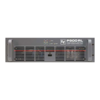
Overview of POWER, STANDBY, PROTECT, OUT, 0 dB, and LIMIT indicator lights.
Details on INPUT A/B, parallel connections, and DSP OUT.
Explanation of CONTROL PORT functionalities on the rear panel.
Information on the RS-232 interface and amplifier address selection.
Details on the CAN-bus for remote control network connections.
Explanation of STATUS LED, EASY REMOTE, and power amplifier output connections.
Details on the GROUND-LIFT SWITCH and MAINS INPUT.
Guidelines for NF (audio) and REMOTE CONTROL NETWORK cabling, including XLR pin assignments.
Technical details on CAN-bus data transfer cabling requirements and specifications.
Power supply and cabling requirements for different operation modes.
Heat dissipation and temperature considerations within the amplifier.
Details on communication interfaces and GPIO control port specifications.
Specifications for power requirements, cooling system, weight, and physical dimensions.
| Channels | 2 |
|---|---|
| Type | Power Amplifier |
| THD | < 0.03% |
| Signal to Noise Ratio (unweighted) | > 105 dB |
| Input Impedance | 20 kΩ balanced |
| Cooling | Variable speed fan |
| Protection | DC |
| Connectors | XLR in |
| Dimensions | 483 mm x 89 mm |
| Voltage | 120V, 230V |
| Weight | 17.2 kg (37.9 lbs) |