Do you have a question about the Electro-Voice P3000RL and is the answer not in the manual?
Crucial instructions to prevent electrical shock, fire, and ensure safe operation of the appliance.
Precautions and requirements for qualified personnel performing maintenance or repair on the unit.
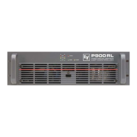
Introduces the P-Series amplifier's advanced technology and the RCM-24 Remote Control Module's capabilities.
Steps for unpacking the amplifier and details on warranty certificate completion and claims.
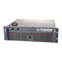
Guidance on proper rack mounting, ventilation, and maintaining safe operating temperatures.
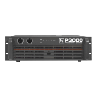
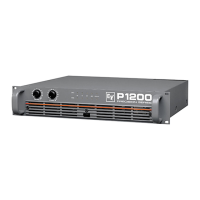
Explanation of the POWER switch and status LEDs (POWER, STANDBY, PROTECT, OUT, 0 dB, LIMIT).
Details on XLR input connectors, parallel connection, and the DSP output signal for audio.
Describes the control port for remote configuration, power-on/stand-by, and signalling internal states.
Information on the RS-232 port for media control systems and setting the amplifier's unique network address.
Explanation of the CAN-bus standard, topology, cabling, and termination for remote control networks.
Covers the STATUS LED for CAN-bus monitoring and the EASY REMOTE function for power control.
Details SPEAKON outputs for channels and bridged mode, and the ground-lift switch for noise loop elimination.
Explains the integrated limiter and how to configure the bridged mode operation for increased power.
Guidance on using balanced XLR cables for audio signal connections, emphasizing noise reduction.
Details on setting up the CAN-bus network, including PC interface (UCC1) and participant limits.
Illustrative diagrams showing common wiring configurations for CAN-bus networks with multiple amplifiers.
Presents complex network configurations, multi-rack setups, and monitor bus usage.
Information on CAN-bus data rates, bus length limits, cable types, and impedance for reliable data transfer.
Tables detailing power supply requirements and expected current draw under various operating conditions.
Data on heat dissipation (Pd) and BTU/hr for managing amplifier temperature in rack systems.
Comprehensive data on maximum output power across 8, 4, and 2 Ohm loads and dynamic headroom.
Specifications for the amplifier's frequency response range and damping factor at 1kHz.
Details on signal-to-noise ratio for amplifier and system, plus input sensitivity and voltage levels.
Lists audio processing functions, communication interfaces (CAN-Bus, RS-232), and control port capabilities.
Information on power input, protection circuits, cooling methods, and physical dimensions.
Schematic illustration of the internal components and signal flow within the power amplifier.
Schematic illustration of the RCM-24 Remote Control Module's internal structure and connections.
Detailed technical drawings showing the physical dimensions and measurements of the amplifier unit.
| Channels | 2 |
|---|---|
| Output Power (2 ohms) | 1500 W |
| Output Power (Bridge 4 ohms) | 3000 W |
| THD | < 0.1% |
| Signal-to-Noise Ratio | > 100 dB |
| Input Impedance | 20 kOhms |
| Voltage Gain | 32 dB |
| Frequency Response | 20 Hz - 20 kHz |
| Input Sensitivity | 1.4 V |
| Signal to Noise Ratio (unweighted) | > 100 dB |
| Input Impedance (unbalanced) | 10 kOhms |
| Cooling | Convection |
| Dimensions (inches) | 19 x 3.5 x 15.5 |
| Weight (lbs) | 35 |