X-Array™ Loudspeaker Systems
angles between enclosures also applies to the
Xrss when determining angles between the top
enclosure and the ATM grid:
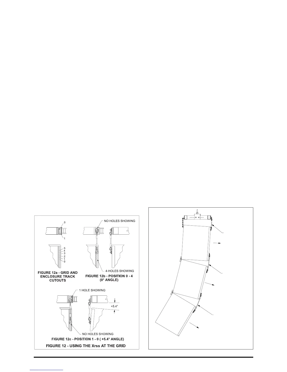
Angle = 7.2°- (Holes Showing) x 1.8°
for the Xrss
where negative (“-”) angles indicate down-
ward angles and positive (“+”) angles indicate
upward angles.
For example, when the short Xrss straps are used
between the ATM grid and the top enclosure for
0° relative angle between the two (position “0-4”),
there are 4 holes showing as illustrated in
Figure 12b. This means that the formula for the
short Xrss strap must be offset by 4 compared to
the long Xrsl strap; or in this example, 7.2° -
(4 x 1.8°) = 0°. If the fittings on the Xrss short
straps are inserted into track cutout #1 on the grid
and track cutout #0 on the top enclosure (position
“1-0”), as shown in Figure 12c, one hole is show-
ing and the top enclosure is angled 7.2° -
(1 x 1.8°) = +5.4° upward relative to the grid.
Multiple Enclosure Angles: The relative vertical
angle between the grid and the top enclosure or
between adjacent enclosures is determined by
the attachment position of the Xrss and Xrsl rig-
ging straps in the rigging track in the grid and en-
closures. Note that the straps set the
relative
angles
between grid and enclosures, and that
those relative angles are
cumulative
when deter-
mining the
absolute angle
of the enclosures lower
in the array. This is best illustrated by the ex-
ample shown in Figure 13.
An Xrss rigging strap is attached at position 1-5
between the ATM grid and the top enclosure,
resulting in a relative angle between the grid and
enclosure of -3.6°. (See the sections immediately
above for how to calculate the relative angles
based on the rigging strap attachment locations.)
Since the grid is level at 0°, the absolute angle of
top enclosure is -3.6° (pointing down). Moving
down the array, an Xrsl rigging strap is attached
in position 1-2 between the first and second en-
closures, resulting in a relative angle of -5.4° be-
tween the two. In other words, the second
enclosure is angled down 5.4° more than the top
enclosure, making the absolute angle of the sec-
ond enclosure -3.6° -5.4° = -9.0°. Finally, an Xrsl
rigging strap is attached at position 2-2 between
the second and third enclosure, resulting in a
relative angle of -7.2° between the two. In other
words, the third enclosure is angled down 7.2°
more than the second enclosure, making the ab-
solute angle of the third enclosure -3.6° -5.4°-7.2°
= -16.2°. Thus, the absolute vertical angle of any
enclosure in an array, is the sum of all of the rela-
tive angles of the enclosures above.
2.3 Adjusting Horizontal Angles
When using the ATM Fly-Ware
TM
MEGS-4000-T
grid, the horizontal shape (the splay angles be-
tween array columns) of a loudspeaker array is
FIGURE 13 - THE RELATIVE ENCLOSURE ANGLES
ADD IN A COLUMN
POSITION1-2(-5.4°)
POSITION1-5(-3.6°)
-9.0°
POSITION2-2(-7.2°)
-16.2°
-3.6°
Xrss
Xrsl
Xrsl
page 12