Do you have a question about the Electrolux EI30GS55JSB and is the answer not in the manual?
Covers warnings on grounding, floor coverings, air flow, child safety, and flammable vapors.
Guidance on preparing countertops for range installation, including edge shaving and tile work.
Details on connecting the gas supply line to the pressure regulator, including precautions.
Ensuring proper grounding of the appliance for electrical safety and shock prevention.
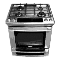
Basic steps for installing the range, including placement and initial fitting into the cabinet opening.
Details on installing with backguards, end panels, or side panels for customized fit.
Instructions for leveling the range using its built-in leveling mechanisms for optimal performance.
Ensuring correct placement of burner caps and heads for proper cooktop function.
Procedure for restoring power and gas supply after installation.
Verifying that the electric igniters function correctly for all burners.
Fine-tuning the low flame setting on standard surface burners for optimal performance.
Adjusting the low flame setting for both portions of the dual surface burner.
Checking the operation of oven burners and understanding their ignition and heating cycles.
Adjusting the air shutter for the oven burner to ensure proper flame color and combustion.
Adjusting the air shutter for the broil burner to ensure proper flame color and combustion.
Locating serial numbers and finding information for service calls and troubleshooting.
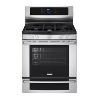
| Type | Freestanding |
|---|---|
| Fuel Type | Gas |
| Product Type | Range |
| Number of Burners | 5 |
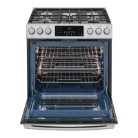
| Self-Cleaning | Yes |
| Wi-Fi Connectivity | No |
| Color | Black Stainless Steel |
| Convection | Yes |
| Warming Drawer | Yes |
| Weight | 200 lbs |
| Width | 30 in. |
| Depth | 28.5 in. |
| Height | 47 inches |