ii contents electrolux EPV09CRA & EPV12CRA electrolux EPV09CRA & EPV12CRA contents iii
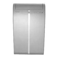
1 Transmitter
2 Display
3 ON/OFF Button
4 DISPLAY On/Off Button
5 TEMPERATURE Buttons
6 PLASMACLUSTER Button
7 OFF 1 HR Button
8 MODE Button
9 TIMER ON Button
10 FAN Button
11 TIMER OFF Button
12 CANCEL Button
13 SWING Button
14 RESET Button
15 TURBO Cool Button
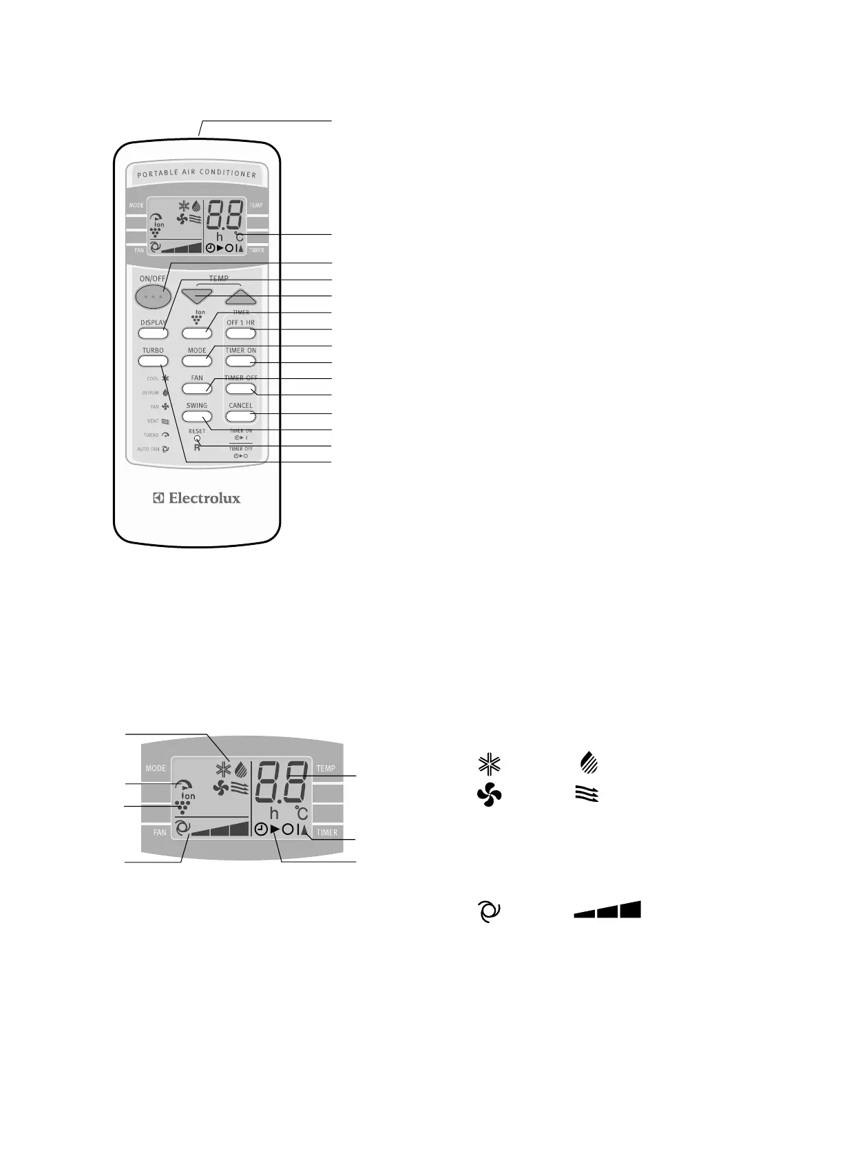
16 MODE SYMBOLS
: COOL : DEHUMIDIFICATION
: FAN : VENTILATION
17 TURBO COOL SYMBOL
18 PLASMACLUSTER SYMBOL
19 FAN SPEED SYMBOLS
: AUTO : Manual setting
20 TEMPERATURE AND TIMER COUNT
DOWN INDICATOR
21 TRANSMITTING SYMBOL
22 TIMER ON/TIMER OFF SYMBOL
1
2
3
4
5
6
7
8
9
10
11
12
13
14
15
16
17
18
19
20
21
22
1 Transmitter
2 Display
3 ON/OFF Button
4 DISPLAY On/Off Button
5 TEMPERATURE Buttons
6 PLASMACLUSTER Button
7 OFF 1 HR Button
8 MODE Button
9 TIMER ON Button
10 FAN Button
11 TIMER OFF Button
12 CANCEL Button
13 SWING Button
14 RESET Button
15 TURBO Cool Button
16 MODE SYMBOLS
: COOL : DEHUMIDIFICATION
: FAN : VENTILATION
17 TURBO COOL SYMBOL
18 PLASMACLUSTER SYMBOL
19 FAN SPEED SYMBOLS
: AUTO : Manual setting
20 TEMPERATURE AND TIMER COUNT
DOWN INDICATOR
21 TRANSMITTING SYMBOL
22 TIMER ON/TIMER OFF SYMBOL
1
2
3
4
5
6
7
8
9
10
11
12
13
14
15
16
17
18
19
20
21
22
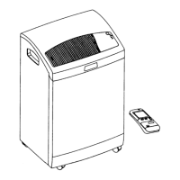
Remote control
Remote control display
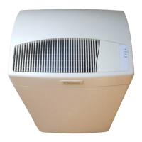
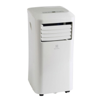
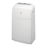
Front view
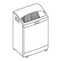
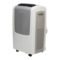
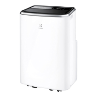
Rear view
1 Air Outlet
2 Vertical louvres
3 Horizontal louvres
4 PLASMACLUSTER Lamp (blue)
5 Remote control signal receiver
window
6 MANUAL Button
7 OPERATION Lamp (red)
8 TIMER Lamp (orange)
9 TURBO COOL Lamp (green)
10 Air inlet
11 Exhaust air outlet
12 Exhaust adapter
13 Exhaust hose
14 Remote control hook
15 Air filters
16 Drainage nozzle and stopcock (upper)
17 Power supply cord hooks
18 Drainpipe nozzle and stopcock (lower)
19 Power supply cord
20 Power plug
21 Casters (4)
1
2
3
4
5
6
7
8
9
10
10
10
11
12
13
14
15
16
17
18
19
20
21
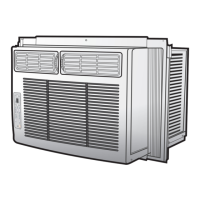
NOTE: Actual unit may vary slightly from above illustration.
 Loading...