CCoommppoonneenntt TTeeaarrddoowwnn
4-11
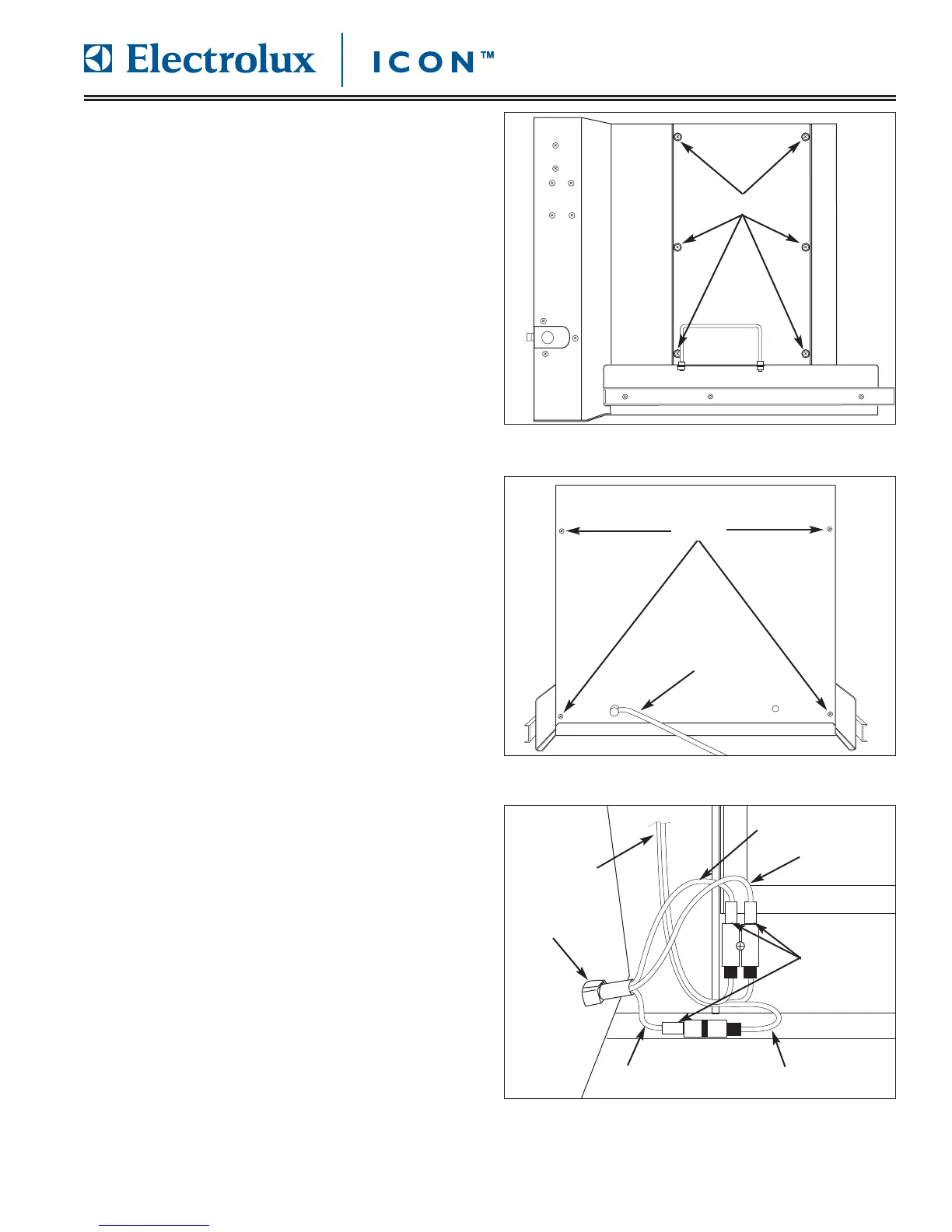
RRiigghhtt SSiiddee AAcccceessss PPaanneell RReemmoovvaall
The right side access panel provides access to the
electronic components of the unit. Screws secure the
access panel to the unit frame.
To remove right side access panel (See Figure 4-21):
1. Pull unit out from installation and remove from the
installation cavity if needed.
2. Remove top stainless steel cover.
3. Using a phillips head screwdriver, extract the
screws from access holes in the panel. Remove
panel from unit.
RReeaarr PPaanneell aanndd PPoowweerr CCoorrdd RReemmoovvaall
The rear panel is secured with screws to the unit frame.
To completely remove the rear panel, the power cord
will need to be disconnected from the wire harness.
To remove the rear panel (See Figure 4-22):
1. Pull unit out from installation and remove from the
installation cavity.
2. Remove top stainless steel cover assembly.
3. Using a phillips head screwdriver, extract screws
from each corner of rear panel.
4. Lift rear panel upwards until rear panel is free of
base plate lip. Turn rear panel until power cord
connections are visible (See Figure 4-23).
5. Disconnect electrical connections of power cord
from wire harness.
6. Rotate strain relief until flats of strain relief align
with slot, then push strain relief through rear panel.
FFiigguurree 44--2211.. R
Riigghhtt SSiiddee AAcccceessss PPaanneell RReemmoovvaall
Screws
FFiigguurree 44--2222.. RReeaarr PPaanneell RReemmoovvaall
Screw
Power Cord
FFiigguurree 44--2233.. PPoowweerr CCoorrdd RReemmoovvaall