CCoommppoonneenntt TTeeaarrddoowwnn
4-18
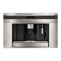
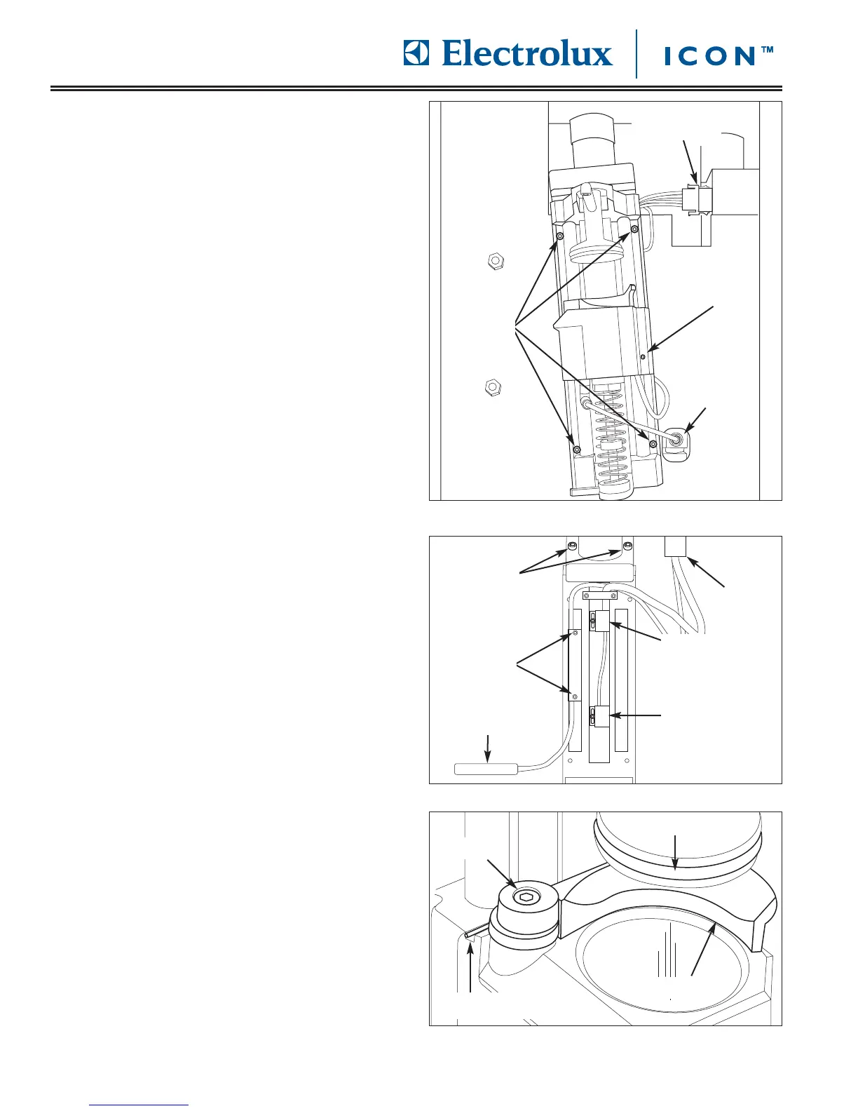
FFiigguurree 44--3377.. BBrreewwiinngg AAsssseemmbbllyy RReemmoovvaall
FFiigguurree 44--3399.. EExxppuullssiioonn TTaabblleett SShhoovveell RReemmoovvaall
FFiigguurree 44--3388..
EExxppuullssiioonn TTaabblleett SShhoovveell RReemmoovvaall
BBrreewwiinngg AAsssseemmbbllyy RReemmoovvaall
The brewing assembly is located behind the coffee
grounds drawer and is secured to the front of the unit
frame with screws.
To remove the brewing assembly (See Figure 4-37):
1. Pull unit out from installation and remove from the
installation cavity.
2. Open door and remove drip tray and coffee
grounds drawer from unit.
3. Remove top stainless steel cover assembly.
4. Inspect the plunger O-ring, replace if worn or
damaged with p/n 02290020. (See Figure 4-39)
5. Remove water line from fitting located at the lower
right of brewing group by pressing in the outer ring
of fitting while pulling water line out of the fitting.
6. Disconnect electrical leads from quick disconnect
located at the top right of inner unit frame.
7. Using a 3mm allen wrench, extract the screws from
each corner of the brewing assembly that secure
the brewing assembly to the unit frame. The top
section of the coffee slide will need to be raised to
access the upper right hand screw.
8. Extract the two screws securing the motor group
mechanism to the top of the brewing assembly,
then lift the motor group mechanism from the
brewing assembly. (See Figure 4-38) Turn the
brewing assembly rod clockwise for the brewer to
rise up until it is in the upper most position. Use a
volt meter and check continuity between the two
leads. To check the lower switch, simply twist the
brewing assembly rod counter clockwise until it
reaches the lowest position. Then check continuity
between the two leads. If a switch needs to be
replaced, remove the leads by using a molex pin
removal tool.
9. To remove the heater, start by taking out the screw
holding it into place. (See Figure 4-37) Then take
out these two screws holding the wiring into place.
(See Figure 4-38) Then take a molex pin removal
tool and remove the two green leads.
10. To remove the expulsion tablet shovel, first the
motor group mechanism must be removed. Then
take out the screw holding the shovel into place.
(See Figure 4-39) When installing the new shovel,
be sure to keep tension on the spring while
installing the screw. The shovel should make a
clicking noise when applying tension to it in its
installation position.
Electrical
Disconnect
Water Line
Remove
Here
Heater
Removal
Screw
Spring Slot
Screw
Plunger O-ring
Screws
Shovel
Motor
Screws
Lower
Switch
Molex
Connector
Screws
Heater
Upper
Switch