-9-
Telephone Line
Terminals 17, 18, 19, 20: The telephone line should be connected (using the
standard Telco wires - minimum 26 AWG) as follows: 17 - Home Tip, 18 - Home Ring,
19 - Telco Tip and 20 - Telco Ring.
Note: The equipment has been approved in accordance with Council Decision 98/482/EC for
pan-European single terminal connection to the public switched telephone network (PSTN).
However, due to differences between the individual PSTNs provided in different countries, the
approval does not, of itself, give an unconditional assurance of successful operation on every
PSTN network termination point. In the event of problems you should contact your equipment
supplier in the first instance.
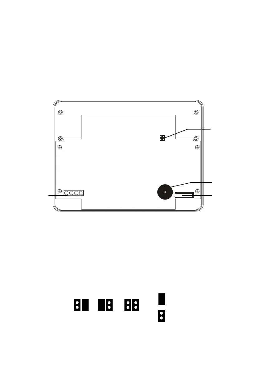
2.4: Mounting the Keypad
1234
Figure 2.4: 3104 LED Keypad (cover removed)
Up to 3 LED keypads can be connected to the Penta control panel. To mount the
keypad:
1. Separate the front and back cover of the keypad by pressing the locking tabs,
situated at the bottom of the keypad, with a small flathead screwdriver.
2. Pull the keypad wires through the opening in the back cover nearest the terminal
block and mount the back cover to the wall.
3. Define the keypad address by configuring jumpers A & B according to the following
diagram.
Jumper
Removed
Keypad 3Keypad 2Keypad 1
Jumper
Installed
Figure 2.5: Keypad Jumper Configuration
Configuration
Jumpers
Buzzer
Tamper
Switch
Terminal
Block