2. PCB assembly
* Follow the instructions step by step. Check off the box after each component has been soldered.
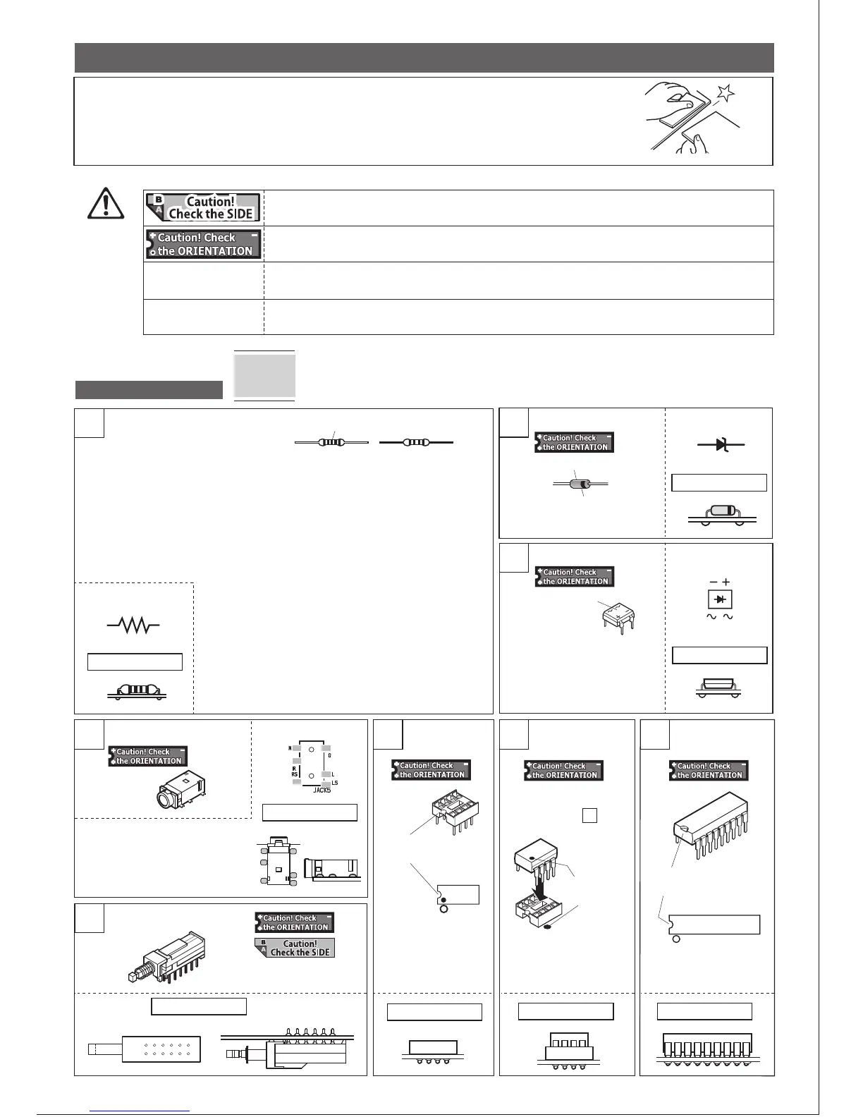
Before soldering
UNIT-1 assembly
1
Resistor (1/4W) [Not orientation specific]
4-pole mini jack
IC socket IC 2068DD IC 40106B,
4040B
Push switch
2
Bridge diode
4
Mark on PCB
Mark on PCB
8500-02
Mark on PCB
Mark on PCB
Mark on PCB
5
Marks of
~,+,-
Zener diode
Correct mounting
Mark on PCB
Mark on PCB
The side with a black line is K.
Made of glass
K
A
□ZD1 □ZD2 □ZD3
□D1
□D2
□D3
□IC1 2068DD
□IC2 2068DD
□JACK5
Match the shapes.
□SW1
□SW3
□IC1
□IC2
①Before soldering, follow the cut lines (grooved lines) on the PCB to break it into 8 pieces.
Use an edge of a desk to break the PCB easily.
②Use a sandpaper or file to make the broken surface smooth to avoid injury.
K
A
In this kit, the components on the right and left channels are assigned even and odd numbers,
respectively. For example, R1 and C1 are Left channel, and R2 and C2 are Right channel.
Most of the components on UNIT-1 PCB are located symmetrically on the board for ease of
locating and mounting the components upon assembly.
Tips
6 7
8
* There will be 5pcs of PCBs, UNIT1-5.
IMPORTANT!
Resistor (1/4W)
2.2Ω (RED-RED-GLD-GLD)
□R59 □R60 □R66
3.3MΩ(ORN-ORN-GRN-GLD)
□R55 □R62
Metal-film resistor(1/4W)
100Ω (BRN-BLK-BLK-BLK-BRN)
□R5 □R6 □R25
□R26 □R53 □R54
390Ω (ORN-WHT-BLK-BLK-BRN)
□R7 □R8 □R21 □R22
10kΩ (BRN-BLK-BLK-RED-BRN)
□R13 □R14 □R23
□R24 □R58
470kΩ (YEL-VIO-BLK-ORN-BRN)
□R27 □R28 □R29
□R30 □R31 □R32
□R33 □R34 □R35
□R36 □R41 □R42
□R51 □R52 □R56
□R57 □R63 □R64
3.3kΩ (ORN-ORN-BLK-BRN-BRN)
□R19 □R20
33kΩ (ORN-ORN-BLK-RED-RED)
□R15 □R16
100kΩ (BRN-BLK-BLK-ORN-BRN)
□R1 □R2 □R3
□R4 □R9 □R10
□R11 □R12 □R17
□R18 □R37 □R38
□R43 □R44 □R45
□R46 □R65
3
Check the indication and make
sure the mounting orientation.
Here are the marks indicating the sides to mount parts and the mounting orientations.
No indication
[Not orientation specific]
Mount the part with this mark on SIDE-B. If this is not shown, mount the part on SIDE-A.
There is a polarity, such as + and -, and has a specific orientation for mounting. If mounted incorrectly,
you may not achieve a proper operation or it can be hazardous for some parts.
There is a polarity, such as + and -, but as the shapes of the parts and the PCB do not allow the parts
to be mounted incorrectly, there is no need to mention the polarity.
There is no polarity, such as + and -, and no specific orientation when mounting.
□D4
□D5
□D6
Set the mini jack so that the jack inlet
faces outward, mount on SIDE-A, and
solder on SIDE-A.
Make sure the jack is fully seated
against
the PCB before soldering.
Insert from SIDE-B,
solder from SIDE-A.
Insert the IC to the socket
mounted in Step 6 .
Match the marks.
Match the shapes.
□IC3 40106B
(or 4584B)
□IC4 4040B
3
Indication by color
2pcs each of 3.3kΩ, 33kΩ, and
100kΩ are to be used in a later
steps.
Correct mounting
Correct mounting
Correct mounting
Correct mounting Correct mounting
Correct mounting
Correct mounting
 Loading...