3.3kΩ
(ORN-ORN-BLK-BRN-BRN)
□R39 □R40
33 kΩ
(ORN-ORN-BLK-RED-BRN)
□R49 □R50
100kΩ
(BRN-BLK-BLK-ORN-BRN)
□R47 □R48
5
□JACK1
□JACK2
□JACK3
□JACK4
□JACK6
Mark on PCB
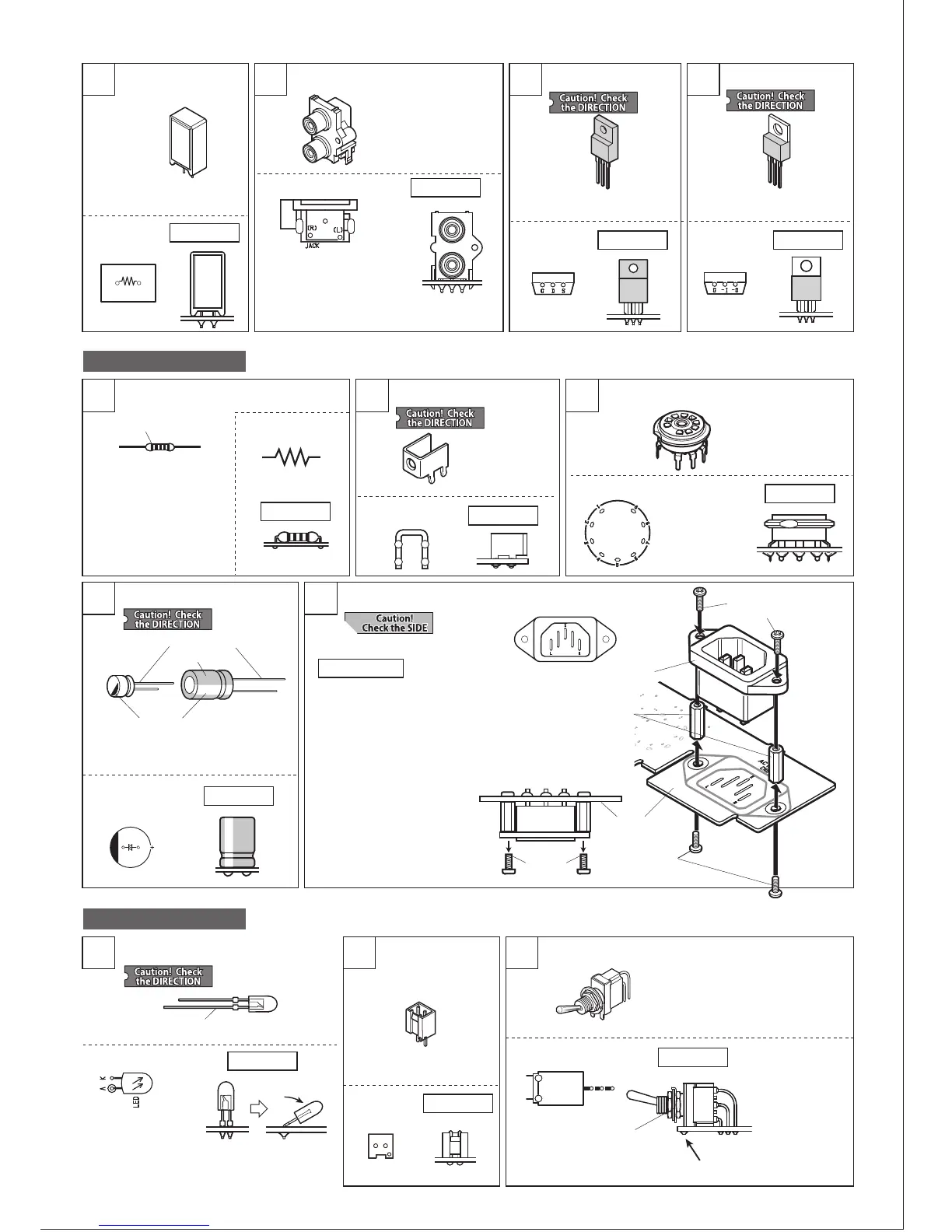
UNIT-1 assembly
2119 20
1
Cement resistor (5W)
[Not direction specific]
Pin jack (RCA jack)
FET 02N60Z
Mark on PCB
How to set
Mark on PCB
How to set
How to install
How to set
Mark on PCB
How to set
22
IC LM2990T-12
□R61 15Ω
(printed either 15Ω or 150
or 15R)
Make sure the jack is fully
seated and level on the PCB
before soldering.
Trim the leads of JACK1 after soldering.
Make sure the
socket is fully
seated and level
on the PCB before
soldering.
□FET 02N60Z
□IC6 LM2990T-12
□V1 □V2
□CN8 AC inlet
□SW4
G
G
-I
-O
D
S
UNIT-2 assembly
Color indication
Metal-film resistor
[Not direction specific]
4 5
2
How to set
Mark on PCB
How to set
How to set
Mark on PCB
Mark on PCB
Mark on PCB
PCB terminal
3
1
UNIT-4 assembly
2 3
Tube socket
□TM3
How to set
Mark on PCB
How to set
Mark on PCB
How to set
Mark on PCB
How to set
Mark on PCB
Electrolytic capacitor
LED Connector 2-pin Toggle switch
AC inlet installation
The side with longer leg is +.
The side with longer leg is A.
Indication
The side with a mark is -.
120μF(20V)
□C13 □C14
□LED
□CN7 2-pin
10μF(200V)
□C17 □C18
①Fix 2pcs of hex spacer to the PCB
SIDE-B with 2pcs of binding screw
small.
②Set AC inlet and temporarily fix it
with 2pcs of binding screw small.
③Solder the terminals of AC inlet at
3 locations, on PCB SIDE-A.
④Remove the screws used for
temporary fixation in Step ②
AC inlet
Hex spacer
(2pcs)
Binding screw
small (2pcs)
Binding screw small(2pcs)
…For temporary fixation
PCB
(SIDE-B)
Temporary
fixation
Make sure the
switch is set
closely and
horizontally to
the PCB upon
soldering.
Tilt for 30-45 degree,
not 90 degree.
* The pins may be bent. Adjust them
with long-nose pliers to match PCB
holes before mounting.
Solder the fixing pin as well.
The nut and washer
will be used in a
later step.
8500-02
Set the LED at the
right angle first, and
solder. Then bend the
leads as shown on
the right.
 Loading...