Do you have a question about the Elektro-Automatik PSB 91000-40 3U and is the answer not in the manual?
| Output Voltage Range | 0 - 1000 V |
|---|---|
| Output Current Range | 0 - 40 A |
| Number of Channels | 1 |
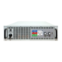
| Form Factor | 3U |
| Cooling | Forced Air |
| Efficiency | > 93% |
| Relative Humidity | 5% to 95% non-condensing |
| Interface | USB |
| Protection Features | OTP |
| Operating Temperature | 0 to 50 °C |
| Storage Temperature | -20 to 70 °C |
Describes the intended use of the equipment as a variable voltage/current source or sink.
Provides crucial safety notices regarding hazardous voltage and general operating precautions.
Explains the meaning of various alarm signals (OT, OVP, OCP, OPP, PF) provided by the equipment.
Provides general technical specifications for the display and control elements of the device.
Lists specific technical data for 400V/480V models, covering power, resistance, and analog interface.
Details specific technical data for 208V models, highlighting differences from EU models.
Describes the control panel elements including touchscreen, rotary knobs, and USB port.
Provides a general overview of the PSB 9000 3U series as bidirectional power supplies with energy recovery.
Explains the status display and how rotary knobs are assigned to functions for value adjustment.
Provides instructions and recommendations for physically installing the device in various locations.
Outlines critical safety procedures and considerations before installing and using the device.
Provides instructions and recommendations for physically installing the device in various locations.
Details the procedures and safety precautions for connecting the device to an AC power supply.
Explains the AC connection schemes and wiring cross-sections for 208V models.
Explains the installation concept for energy recovering devices, focusing on grid feedback and safety.
Provides detailed instructions for connecting DC loads or DC sources, including cable considerations.
Outlines the procedures for initial commissioning of the device after installation.
Explains the different operating modes (CV, CC, CP, CR) and their characteristics.
Details the Constant Voltage (CV) operating mode and transient time after load steps.
Explains Current Regulation (CC) mode, including power limiting behavior.
Describes Power Regulation (CP) mode and its operation principles.
Provides an overview of device alarms and their potential causes.
Details the Safety OVP feature, specific to 60V models, for protection against excess voltage.
Guides users through configuring operating parameters via the device's MENU system.
Guides users through configuring operating parameters via the device's MENU system.
Continues the overview of the Function Generator menu, detailing Battery Test and MPP Tracking modes.
Provides further details on General Settings, including analog interface parameters and DC terminal behavior.
Explains how to configure adjustment limits for voltage, current, power, and resistance.
Details manual adjustment of voltage, current, power, and resistance values using rotary knobs or direct input.
Explains how to manually or remotely switch the DC terminal on and off.
Provides a general overview of remote control capabilities via analog, USB, or optional interface modules.
Details how to use the analog interface for remote control, including its capabilities and limitations.
Provides an overview of device alarms and their potential causes.
Describes how to lock the HMI to prevent accidental alterations of values.
Details how to load and save user profiles, which store settings and set values.
Introduces the built-in function generator (FG) for creating various signal forms and applying them to set values.
Guides manual operation of the function generator, including function selection, parameter adjustment, loading, starting, and stopping.
Continues examples for the arbitrary function, illustrating different waveform generation scenarios.
Details how to configure and work with the PV table function, including parameter adjustment and simulation.
Introduces the extended PV table function for testing solar inverters, detailing differences and parameters.
Provides a step-by-step guide for configuring the extended PV table function.
Explains the purpose and modes of the battery test function for charging and discharging batteries.
Covers saving result data from MPP4 mode to USB and remote control of the function generator.
Covers alarms and problem situations in master-slave operation, and important considerations for inactive units.