15
www.elektror.com
Operating and assembly instructions RD
9016306 06.22/17
EN
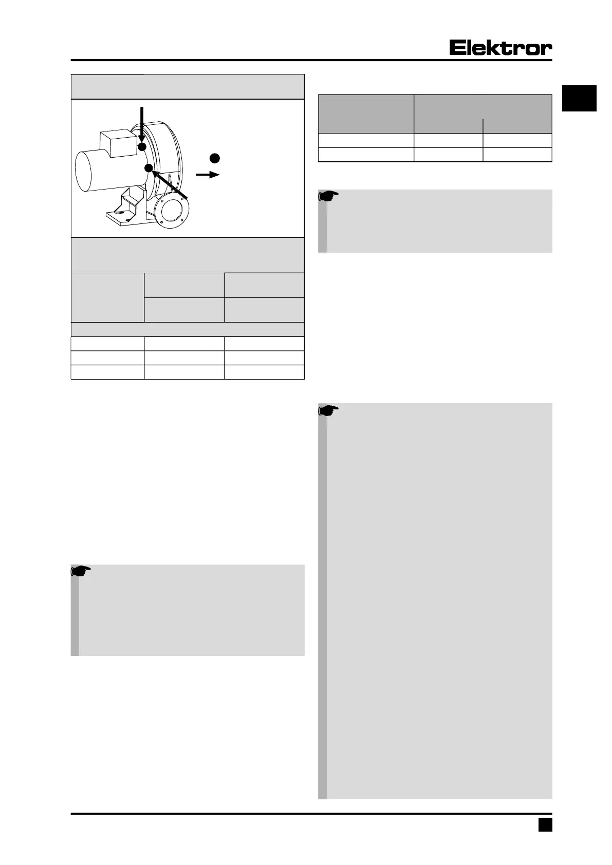
Measurement on the fl ange bearing shield,
as close as possible to the bearing
= Measuring point
= Measuring
direction
Maximum permissible vibration speed
(Limit values according to ISO 14694:2003 (E),
category BV-3)
Rigidly mounted
[mm/s]
Flexibly mounted
[mm/s]
Eff ective value
[r.m.s.]
Eff ective value
[r.m.s.]
At installation
Start-up 4,5 6,3
Alarm 7,1 11,8
Shut-down 9,0 12,5
• Standard blowers with base:
Bolt securely to a level and fi rm surface at the place of
use, making sure that the surface has adequate load-
bearing capacity and avoiding vibration transmission or
vibrational load.
• Other standards and regulations must be observed
depending on the application.
• Blower feet and consoles must be designed only for the
respective blower’s own weight.
• Cover the open air intake and discharge with protective
grilles according to DIN EN ISO 13857.
• Ensure that the motor has adequate ventilation.
Permitted ambient temperatures with:
Standard model with Elektror motor and a rated voltage of
50 Hz or 60 Hz:
• Ambient temperature -20°C to +60°C
Note!
The rated effi ciencies and the effi ciency classes
of the motors are given as per IEC 60034-2-1 for
operation at an ambient temperature of 25°C.
As per IEC 60038 Elektror motors are generally
designed for an extended voltage range of ±10%.
However, the stated effi ciency relates to the rated
voltage, i.e., the extended tolerance is not taken
into account.
Special voltages, multi-voltage motors, models suitable for
frequency converters, FUK models, devices with UL ap-
proval, devices with Aircontrol and other motor makes:
• Ambient temperature -20°C to +40°C
• Voltage tolerance ±5% (For exceptions, see „4.2 Fre-
quency converter operation“)
• The drive motor ventilation system must not be aff ected
by the installation situation.
Minimum distance to the blower cover (for the intake of
cooling air)
Drive power
Minimum distance
to the blower cover
[mm] [inches]
≤ 1.5 kW 34 1.34
> 1.5 kW 53 2.09
3.3 Electrical connection
Note!
The work described in this section may only be
performed by a qualifi ed electrician. Connect the
appliance to the power supply in the terminal box
as per the wiring diagram and observing the
applicable local regulations.
Three-phase or a.c. motors can be used as drive motors.
In the appliance designation, the letter D stands for three-
phase a.c. and the letter E for single-phase a.c.
• The drive motor has to be safeguarded by a motor circuit
breaker (this does not apply to frequency-converter-
operated appliances). Where appliances are frequency-
converter-operated, the existing temperature sensor (PTC
resistor sensor) or temperature switch (normally closed
contact) must be connected to the converter and
evaluated.
• Check to see if the mains voltage matches the voltage
specifi ed on the rating plate.
• The safety earth terminal can be found in the terminal box.
Note!
The following information should also be ob-
served when operating the drive motor with a
frequency converter:
• Only motors must be used on the frequency
converter that are marked on the rating plate with
the option “/FU”, “suitable for use with a frequen-
cy converter” or that were ordered and confi rmed
as “suitable for use with a frequency converter”.
• The frequency converter supply voltage must
only be a maximum of 400 V without the motor fi l-
ter. Appropriate measures such as a motor fi lter to
protect the motor must be installed on the motor
terminals with higher frequency converter supply
voltages, longer lines and/or if the pulse voltages
are exceeded (max. 1000 Vpk for drive motors up
to 0.75 kW, maximum 1300 Vpk for drive motors
larger than 0.75 kW) Please contact the converter
supplier in this case. If a motor fi lter is included
in the delivery, this must be installed between the
converter and the motor. Please ensure that there
is suffi cient space in the switch cabinet and take
into account the installation and assembly require-
ments in the operating instructions of the frequen-
cy converter/motor fi lter manufacturer.
• The maximum cable length between the mo-
tor and switch cabinet frequency converter (e.g.
Lenze Vector, Omron MX2 and Omron RX) must
not exceed 20 m. Maximum cable lengths of up to
3 m are permitted with Kostal INVEOR frequency
converters installed close to the motor and up to
10 m with Lenze MOTEC frequency converters.
Further information on wall mounting close to the
motor can be found in the original operating and
assembly instructions of the respective frequen-
cy converter manufacturer. The electrical con-
necting cables between the motor and frequency
converter in the above cases must be suitable
shielded cables, laid using the shortest route and
 Loading...