Do you have a question about the Elenco Electronics AM/FM-108TK and is the answer not in the manual?
Guide to identifying resistor values using color bands and their meanings.
Explanation of how capacitor values and tolerances are printed.
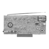
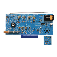
Explains the superheterodyne design and the breakdown into 9 assembly sections.
Essential safety precautions to follow during soldering and assembly.
Illustrates good and poor soldering connections for successful assembly.
Guides on how to test NPN and PNP transistors using an ohmmeter.
Instructions for testing diodes using an ohmmeter to check forward and reverse bias.
Describes the function of the audio amplifier stage in increasing audio power.
Detailed instructions for installing components on the PC board for Section 1.
Tests the circuit's idle current draw with power ON.
Checks the voltage at TP1 to ensure proper operation.
Measures transistor bias voltages for correct operation.
Explains and guides the calculation of the audio amplifier's DC gain.
Guides on measuring the AC gain of the audio amplifier circuit.
Procedure to measure the audio amplifier's AC bandwidth using an oscilloscope.
Tests for distortion, maximum power output, and amplifier efficiency.
Explains the AM detector's role in changing IF to audio and AGC's function.
Instructions for installing components for the AM detector and AGC stage.
Tests to verify component installation and voltage levels.
Tests the AM detector and AGC circuit functionality.
Verifies overall system performance after stage assembly.
Explains the role of the second IF amplifier in gain and selectivity.
Instructions for installing components for the second AM IF amplifier.
Tests to verify bias voltage for transistor Q9.
Measures AC gain and bandwidth of the second AM IF amplifier.
Explains the first IF amplifier's function, AGC impact, and gain.
Instructions for installing components for the first AM IF amplifier.
Tests for Q8 base bias and current to ensure proper operation.
Measures AC gain and tests the AGC circuit's effect on signal level.
Explains how radio waves are mixed with local oscillator for IF signal.
Tests for Q7 bias voltage and checks for oscillation.
Measures DC voltage at the base of transistor Q7 for bias verification.
Tests the AM oscillator circuit's output and tuning behavior.
Procedure for aligning IF, Detector, and Oscillator stages without test equipment.
Procedure for aligning IF amplifiers using RF generator and oscilloscope.
Adjusting antenna coil and trimmer for optimal AM reception and tracking.
Provides DC voltage readings for troubleshooting the AM section.
Explains the function and operation of the FM ratio detector circuit.
Instructions for installing components for the FM radio section.
Tests for FM voltage and transistor current.
Measures FM stage voltage and calculates transistor Q6 current.
Measures the AC gain of the ratio detector circuit.
Procedures for aligning the FM ratio detector using various methods.
Explains the second FM IF amplifier's role in gain and bandwidth.
Instructions for installing components for the second FM IF amplifier.
Tests for Q5 bias voltage.
Measures AC gain and bandwidth of the second FM IF amplifier.
Explains the first FM IF amplifier's gain and operation.
Instructions for installing components for the first FM IF amplifier.
Tests for Q4 bias voltage.
Measures AC gain and bandwidth of the first FM IF amplifier.
Explains mixer operation and how the IF signal is produced.
Measures the bandwidth of the FM oscillator circuit.
Instructions for assembling the FM oscillator components.
Tests for Q2 bias and the AFC circuit's function.
Measures Q2 bias and explains AFC voltage's effect on oscillator.
Steps for aligning IF, Detector, and Oscillator without test equipment.
Aligns the FM IF amplifiers to achieve maximum gain.
Optimizes the ratio detector alignment for best performance.
Sets the FM oscillator range for optimal frequency tracking.
Aligns the RF stage to track the FM oscillator for optimal reception.
Provides DC voltage readings for troubleshooting the FM section.
Lists technical specifications for audio, AM, and FM radio performance.
| Type | AM/FM Radio Kit |
|---|---|
| Tuning | Analog |
| FM Frequency Range | 88 - 108 MHz |
| AM Frequency Range | 530 - 1600 kHz |
| Antenna | Telescopic |
| Headphone Jack | Yes |
| Speaker | Included |