15
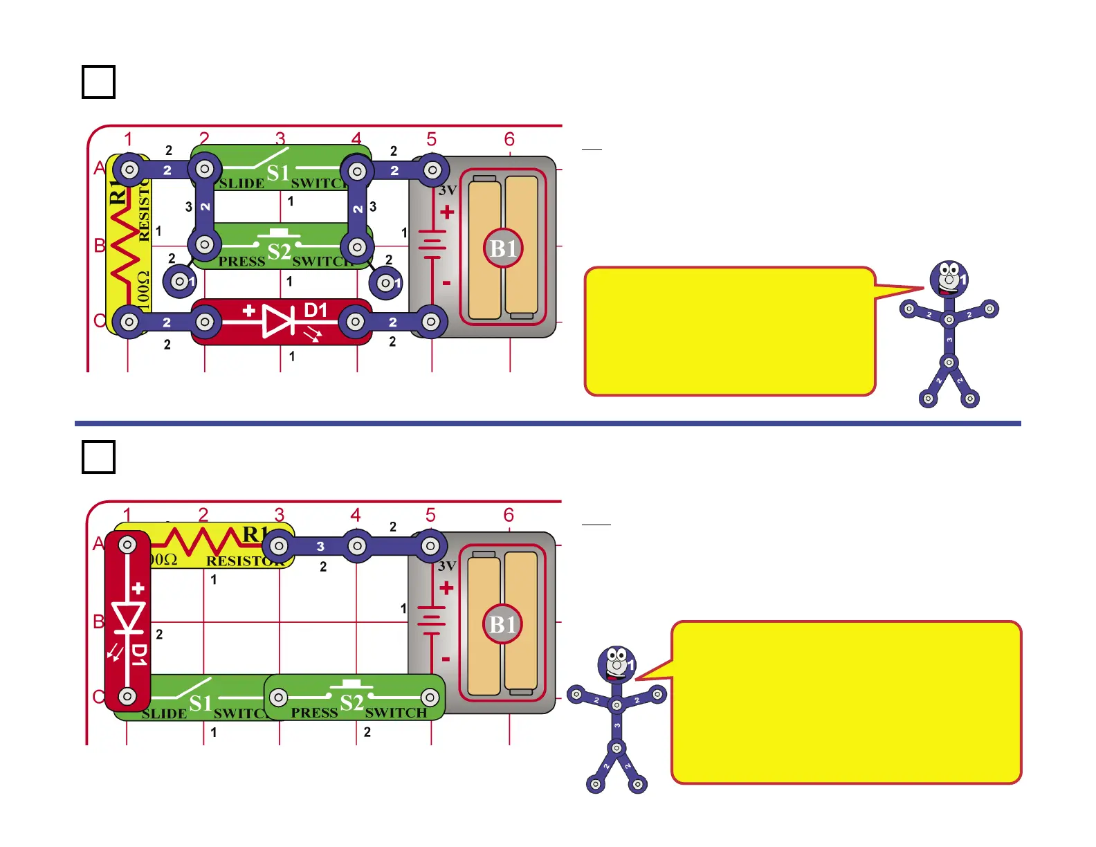
This circuit is commonly called an OR gate.
OR gates are used in digital logic circuits to
perform logical additions. When one of the
inputs is high (one of the switches is on) the
output is high (LED on). The output will only
be low (LED off) if both inputs are low (both
switches are off).
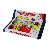
This circuit is commonly called an AND gate. AND
gates are used in digital logic circuits to perform
logical multiplies. When one of the inputs is low (one
of the switches is off) the output is low (LED off). The
output will only be high (LED on) if both inputs are high
(both switches are on). Combinations of AND and OR
circuits are used to add and multiply numbers together
in modern computers. These circuits are made of tiny
transistors in massive integrated circuits.
This OR That
Build the circuit shown. Notice that if you turn on the slide switch (S1)
OR press the press switch (S2) the LED (D1) lights up. There is no
partially lit state here, the diode is either totally on or totally off. While this
may seem very simple and boring, it represents an important concept in
electronics. Two switches like this may be used to turn on a light in your
house, or they might be two sensors at a railroad crossing used to start
the ding-ding sound and lower the gate. You could also have more than
two switches and the circuit would function the same way.
This AND That
Build the circuit shown. Notice that if you turn on the slide switch (S1)
AND press the press switch (S2) the LED (D1) lights up. Once again,
there is no partially lit state here, the LED is either totally on or totally
off. Two switches like this may be used to turn on the same light in your
house, the room switch and the master switch in the electrical box. You
could also have more than two switches and the circuit would function
the same way.
Project 93
Project 94