17
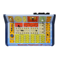
Power Pitch
In the circuit, the outputs from the alarm (U2) and music ICs are
connected together. Build the circuit shown and then place the alarm
IC (U2) directly over the music IC (U1), resting on three 1-snaps. Turn
on the slide switch (S1) and you will hear a siren and music together.
Push the press switch (S2) and the fan spins, while the sound may not
be as loud. The fan may rise into the air when you release the switch.
This circuit is similar to Project #47, but the fan will y a little higher
since the sound circuit no longer drives the lamp (L1) and therefore
uses less battery power.
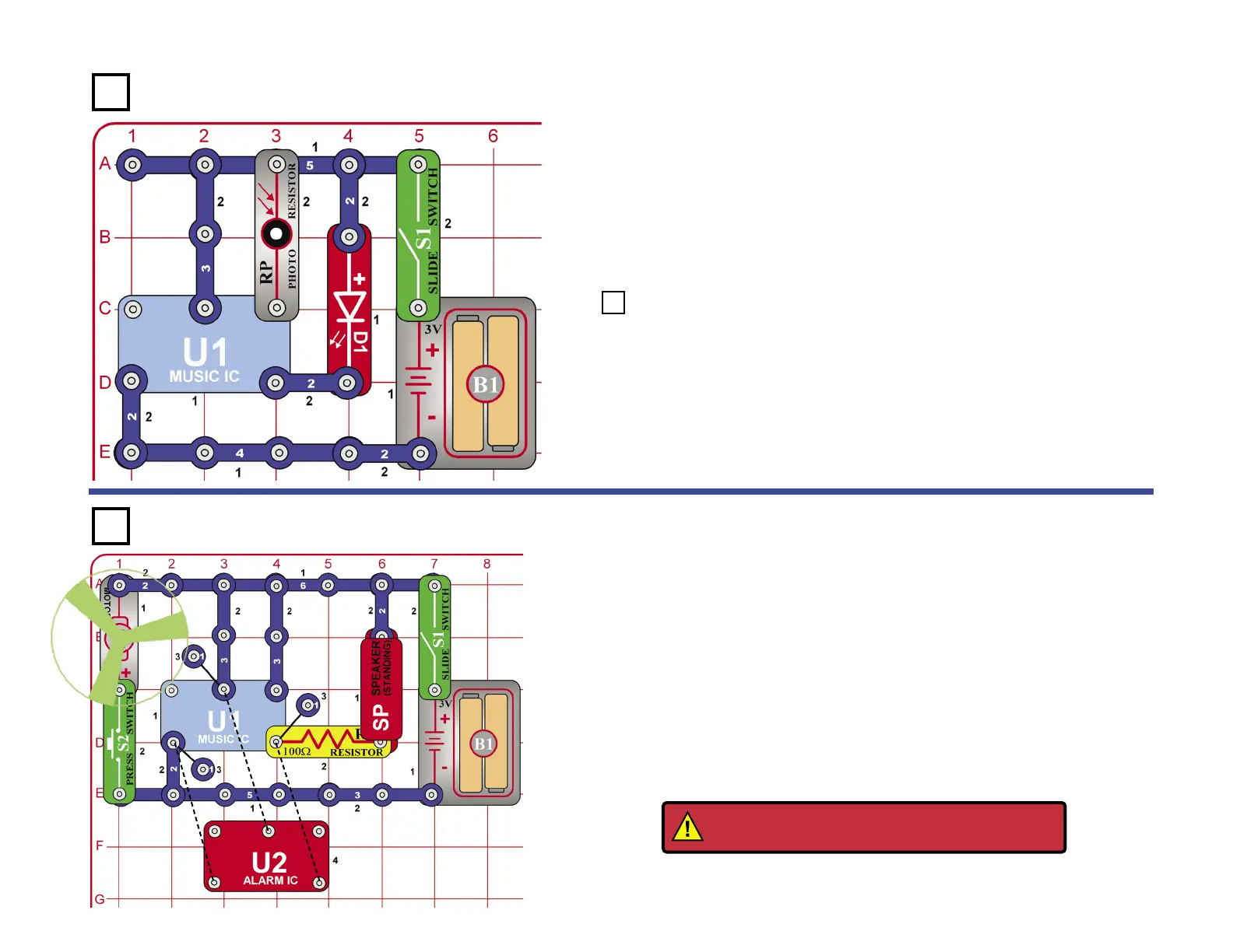
Light Makes Light
Build the circuit to the left. Cover the photoresistor, turn the switch on, and
notice that the LED is on for several seconds and then goes off. Uncover
the photoresistor and place the unit near a light and the LED will light. Cover
the photoresistor (RP) again and the LED will turn off. The resistance of
the photoresistor decreases as the light increases activating the U1 IC that
varies the voltage to the LED making it light.
Use the preceding circuit. Connect the motor (M1) across points A1
and C1 on the base grid, and remove the photoresistor (RP). Turn the
switch on and the LED (D1) lights for several seconds then goes out.
Turn the shaft of the motor and the LED will light again. As the motor
turns, it produce a voltage. There is a magnet and a coil inside the
motor. When the axis turns the magnetic eld will change and generate
a small current through its terminals. This voltage then activates the
music IC.
Project 98 Go & Glow
Project 97
Project 99
WARNING: Moving parts. Do not touch the fan or
motor during operation. Do not lean over motor.