List of Figures
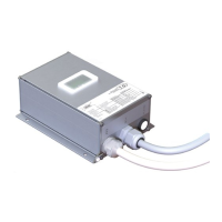
Figure 1: Type label for identification of the Safe Box ................................................................................. 16
Figure 2: Info label with additional information ......................................................................................... 16
Figure 3: Safe Box dimensions ................................................................................................................. 17
Figure 4: Neutral conductor connection to avoid door contact bridging by indicator circuit ........................... 22
Figure 5: PCB Layout to avoid door contact bridging by indicator circuit ...................................................... 22
Figure 6: Type designation ...................................................................................................................... 23
Figure 7: Installation circuit diagram for LIMAX Safe SC with (semi-)guided Sensor ....................................... 27
Figure 8: Installation circuit diagram for LIMAX Safe SC with unguided Sensor ............................................. 28
Figure 9: Circuit diagram of LIMAX Safe SG with (semi)guided sensor, SGC connected to an
electromechanically driven blocking device on the speed governor ................................................. 29
Figure 10: Circuit diagram of LIMAX Safe SG with unguided sensor, SGC connected to an electromechanically
driven blocking device on the speed governor ............................................................................... 30
Figure 11: Circuit diagram of LIMAX Safe SG, SGC connected to an electromechanically driven safety gear
(guided Sensor) .......................................................................................................................... 31
Figure 12: Circuit diagram of LIMAX Safe SG, SGC connected to an electromechanically driven safety gear
(unguided Sensor) ...................................................................................................................... 32
Figure 13: Example of an installation which should be avoided (top) and an advantageous installation (bottom).
................................................................................................................................................. 34
Figure 14: Connection diagram for power, CAN communication and reset input ......................................... 35
Figure 15: SGC integration diagram for LIMAX Safe SG ............................................................................ 36
Figure 16: SGC integration diagram for LIMAX Safe SC ............................................................................. 36
Figure 17: Connection of door zone indicator ........................................................................................... 37
Figure 18: Operation modes ................................................................................................................... 39
Figure 19: Components of the Safe Box .................................................................................................... 46
Figure 20: Behavior of the upper limit switches .......................................................................................... 51
Figure 21: LED signals visible through the window ..................................................................................... 54
Figure 22: Electrical sensor connection ..................................................................................................... 57
Figure 23: Dependency final tripping speed as a function of rated speed ..................................................... 81
Figure 24: Dependencies of pre-tripping and final tripping speed as functions of rated speed ....................... 82
List of Tables
Table 1: Pin assignment PIO cable ........................................................................................................... 26
Table 2: Pin assignment SCA cable .......................................................................................................... 26
Table 3: Wire assignment of OC .............................................................................................................. 33
Table 4: Wire assignment of NOC and DCS ............................................................................................. 33
Table 5: Wire assignment inspection control ............................................................................................. 34
Table 6: Wire assignment power supply and battery supply ......................................................................... 35
Table 7: Wire assignment reset input ........................................................................................................ 35
Table 8: Wire assignment of SGC output und SGC-FB input ...................................................................... 35
Table 9: Wire assignment door zone indication ......................................................................................... 37
Table 10: Wire assignment CAN .............................................................................................................. 37
Table 11: Overview safety functions ......................................................................................................... 48
Table 12: Limit switch behavior ................................................................................................................ 50
Table 13: Safety output states in pre-commissioning mode ......................................................................... 53
Table 14: Meaning of LED signals ............................................................................................................ 54
Table 15: Wire assignment power supply and battery supply....................................................................... 55
Table 16: Wire assignment CAN .............................................................................................................. 55
Table 17: Wire assignment of safety relevant actuators .............................................................................. 56
Table 18: Wire assignment door contact input .......................................................................................... 56
Table 19: Wire assignment inspection control ........................................................................................... 56
Table 20: Wire assignment door zone indication ....................................................................................... 57
Table 21: Wire assignment reset input ...................................................................................................... 57
Table 22: Pin assignment sensor connector ............................................................................................... 57
Table 23: Triggering of the safety functions ............................................................................................... 60

 Loading...