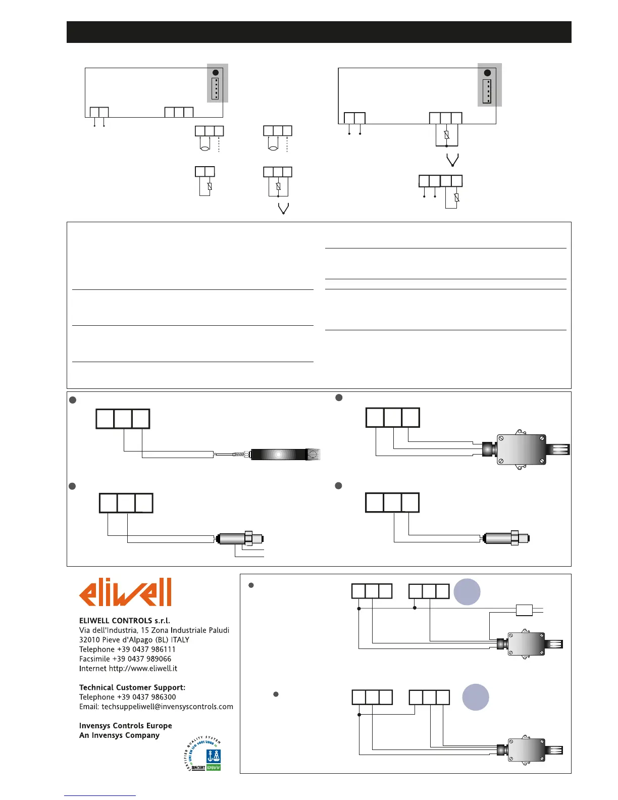
WIRING DIAGRAMS
6/2006 - GB -
cod. 9IS43049
TERMINALS
1 - 2 Power supply
• 230Va ±10% 50/60 Hz or
• 12Va/c ±10% 50/60 Hz or
• 12-24Va ±10%, 12-36Vc ±10% SELV (only models
NTC/PTC & Pt100-TC)
NTC/PTC Models
3 - 4 Pb1 probe input
V Models
3 - 4 - 5 Voltage input (3=GND; 4=signal; 5=+12V)*
I Models
3 - 4 - 5 Current input (3=GND; 4=signal; 5=+12V)*
Pt100-TC Models
4 - 5 TcJ-TcK Input
3 - 4 - 5 Pt100 3 wires Input
LX MODELS ONLY
A TTL input for Copy Card and connection to
TelevisSystem
* according to model
* Check probe connection polarity.
EWHS 300/310 3 wires Power Supply from EM300(LX)
Probe
EWHS 280 2 wires Power Supply from EM300(LX)
Probe
EWPA 007/030 2 wires External Power Supply for Transducer
Transducer
brown
blue
brown
white
GND (only EWHS310)
V+
Power Supply
for Transducer
RH/T
3 4 5
3 4 5
3 4 5
EWPA 007/030 2 wires Power Supply from EM300(LX)
Transducer
brown
white
3 4 5
EWHS 310 HUMID. + TEMP.
Power Supply from external Power Supply
GND
V+
RH
3 4 5
3 4 5
T
230V
GND
GND IN V+
GND IN V+
EWHS 310 HUMID. + TEMP.
Power Supply from EM300(LX)
GND
V+
RH
3 4 5
3 4 5
T
GND
GND IN V+
GND IN V+
EWHS 310
EWHS 310
3 4
Pb1
NTC/PTC
1 2
3 4 5
A
Supply
3 W max
EM300(LX) - 12-24Va
12-36Vc
LX models ONLY
Pt100-TC
+
-
1 2
Supply
3 W max