INTRODUCTION
This section is designed to get you up and running in the shortest possible
time. It contains basic information on the EWRC300 – 500LX.
Should you need more detailed information, please refer to the remainder
of the manual.
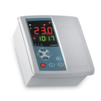
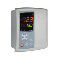
Out of the box, the EWRC300 – 500LX is set up for standard Electrical
Defrost applications.
It can be altered for Hot Gas or Off Cycle applications if needed.
INPUTS / OUTPUTS DEFAULT SETTINGS
Output relays (default settings)
• Out (relay) 1 = Compressor (or liquid line valve)
• Out (relay) 2 = Defrost
• Out (relay) 3 = Evaporator fan
• Out (relay) 4 = Alarm (EWRC500LX only)
• Out (relay) 5 = Light (EWRC500LX only)
Note: It is possible to change the function of each relay, see parameters
H21 to H25
Probe Inputs
• Pb1 = Regulation Probe
• Pb2 = Defrost Termination Probe
• Pb3 = Not required (except in special applications)
MECHANICAL ASSEMBLY
a) Remove the coverplate on the right side of the door, pressing lightly on
the points indicated by the arrows in Figure 1 and open the door.
b) Drill holes in the backplate at the top or bottom to pass the wires through.
See the example in figure 2.
c) Screw the backplate to the wall using 4 screws (not supplied) to match the
holes illustrated in Figure 3.
d) Shut the door by securing it with the 2 screws provided.
Replace the screw caps removed earlier from the door (see point a).
e) The door lock (an optional accessory) can be installed in 3 different
positions on the door, the holes to be drilled are indicated on the back.
Each position on the door represents a different position where the
disconnector can be mounted.
N.B.: to make it easier to wall mount the backplate, remove the door by pres-
sing lightly on the left side (the side that the door is attached by). You will
also have to separate the base from the keypad by disconnecting the keypad
cable.
11
11
22
22
33
33
EWRC 300-500 LX
CC
CC
oo
oo
ll
ll
dd
dd
FF
FF
aa
aa
cc
cc
ee
ee
FF
FF
aa
aa
mm
mm
ii
ii
ll
ll
yy
yy • Quick Start
WIRING DIAGRAM