IC 901 A 5/5
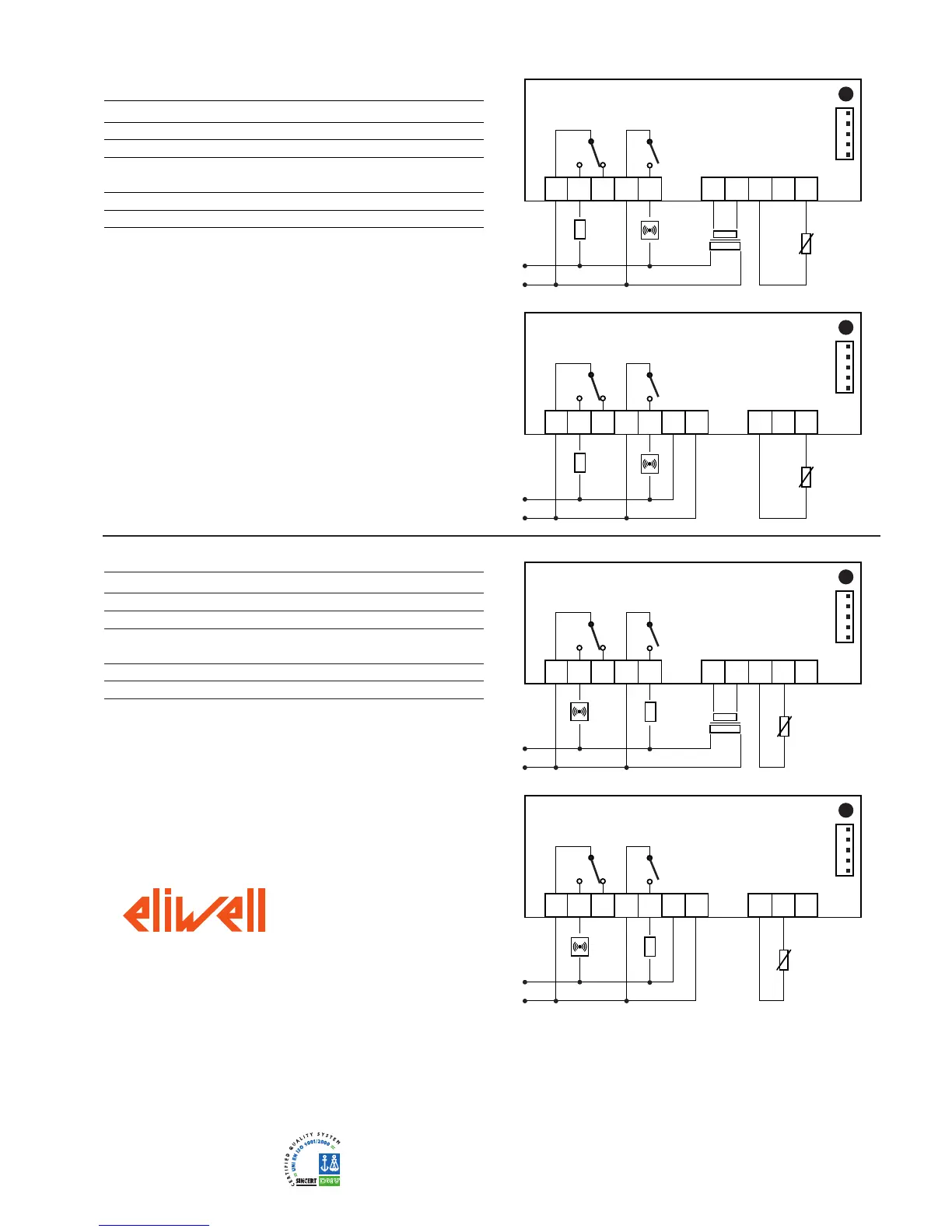
WIRING
1 - 2 N.O. regulator 1 relay output out1
1 - 3 N.C. regulator 1 relay output out1
4 - 5 N.O. regulator 2 relay output (alarm) out2
6 - 7 Power supply 1,5 VA max. (12V version)
Power supply 3 VA max. (230V version)
8 - 10 Probe 1 input (thermostat)
A TTL input for Copy Card
PLEASE NOTE:
• User Default Settings
• for relay capacities check on the instrument label
Wiring diagram
1 2 3 4 5
6 7 8 9
IC 901 A - 12 V
A
10
out1
out2
1 2 3 4 5 6 7
8 9
IC 901 A - 230 V
A
10
out1
out2
1 2 3 4 5
6 7 8
IC 901 A - 12 V
A
10
out1
out2
9
1 2 3 4 5 6 7
8
IC 901 A - 230 V
A
10
out1
out2
9
WIRING
1 - 2 N.O. regulator 1 relay output (alarm) out1
1 - 3 N.C. regulator 1 relay output (alarm) out1
4 - 5 N.O. regulator 2 relay output out2
6 - 7 Power supply 1,5 VA max. (12V version)
Power supply 3 VA max. (230V version)
8 - 10 Probe 1 input (thermostat)
A TTL input for Copy Card
PLEASE NOTE:
• User Default Settings
• for relay capacities check on the instrument label
WARNING:
For 15A version buzzer is not available
Eliwell & Controlli s.r.l.
Via dell'Industria, 15 Zona Industriale Paludi
32010 Pieve d'Alpago (BL) ITALY
Telephone +39 0437 986111
Facsimile +39 0437 989066
Internet http://www.eliwell.it
Technical Customer Support:
Email: techsuppeliwell@invensys.com
Telephone +39 0437 986300
Climate Controls Europe
An Invensys Company