PARAMETER
diF
HSE
LSE
HC
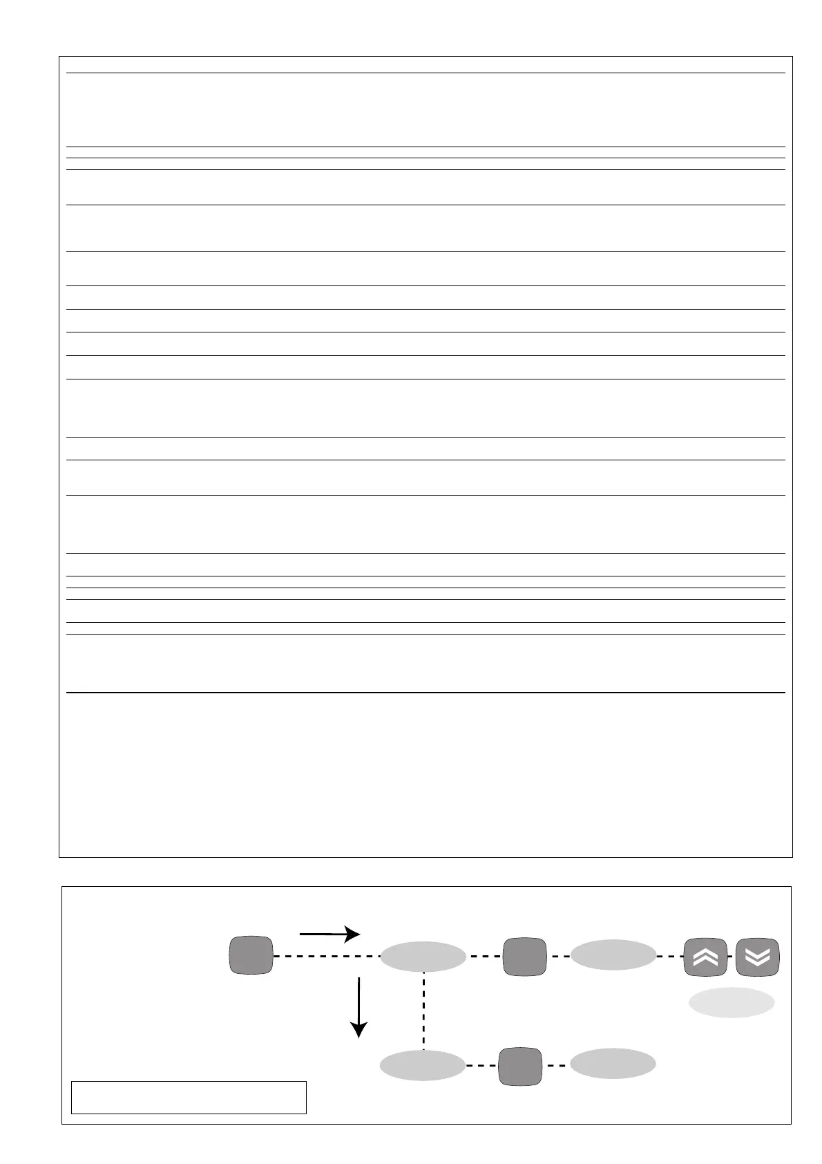
Ont (1)
OFt (1)
dOn
dOF
dbi
OdO (!)
LOC
PA1
CA1
dro
H00 (!)
rEL
tAb
UL
dL
Fr
(1) see Duty Cycle Diagram
* DEFAULT column: for HC, H00 parameters default is depending on model
** VALUE column: to be filled manually, with customized settings (if different from the default value).
*** LEVEL column: indicates the level of visibility of parameters accessible by PASSWORD (see the related paragraph)
(!) WARNING!
• If one or more of these parameters highlighted with (!) are modified, teh controlller must be switched off and switched on again to ensure correct operation.
• It is strongly recommended, anyway to switch off and switch on again the controller anytime parameters have been changed to prevent malfunctioning on configuration
and/or ongoing timings
DESCRIPTION
REGULATOR (folder with “CP”)
Relay regulator tripping differential. The regulator stops on reach-
ing the Setpoint value (as indicated by the adjustment probe), and
restarts at temperature value equal to the Setpoint plus the value
of the differential.
Note: the value 0 cannot be assumed.
Maximum possible setpoint value.
Minimum possible setpoint value.
Heat/Cool Mode. If set to H the generic regulator actuates for hot
operation. If set to C the generic regulator actuates for cold opera-
tion
REGULATOR PROTECTIVE DEVICES (folder with “CP” label)
Regulator activation time in the event of faulty probe. If set to “1”
with Oft at “0”, the regulator is always on, while for Oft >0,
it functions always in duty cycle mode.
Regulator in disabled state time in the event of a faulty probe. If
set to “1” with Ont at “0”, the regulator is always off, while at Ont
>0, it functions always in duty cycle mode.
Delay time in activating the regulator relay after switch-on of
instrument.
Delay after switch off. The indicated time must elapse between
switch-off of the regulator relay and the successive switch-on.
Delay between switch-ons. The indicated time must elapse between
two successive switch-ons of the regulator.
delay time in activating the outputs after switch-on of the instru-
ment or after a power failure. 0= not active.
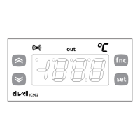
DISPLAY (folder with label “diS”)
Keyboard locking. However, you can enter parameter programming,
modify them and change the status of this parameter to unlock the
keyboard.
y = yes (keyboard locked); n = no.
Password 1. When enabled (value other than 0) it constitutes the
access key for level 1 parameters.
Calibration 1. Positive or negative temperature value added to the
value read on the adjustment room probe (probe 1) before being
displayed and used for adjustment.
Selection of °C or °F to view the temperature read by the probe.
0 = °C, 1 = °F.
PLEASE NOTE: the switch between °C and °F DO NOT modify
setpoint, differential, etc. (for example set=10°C become
10°F).
CONFIGURATION (folder with label “CnF”)
Probe type selection, PTC or NTC. 0 = PTC; 1 = NTC.
Device version. Read only parameter.
Reserved. Read only parameter.
COPY CARD (folder with label “Fpr”)
UpLoad: transferring parameters from instrument to Copy Card.
downLoad: transferring parameters from Copy Card to instrument.
Format. Erasing all data in the copy card.
PLEASE NOTE: using “Fr” parameter (copy card formatting)
the data within the copy card will be lost permenently. The
operation cannot be cancelled.
Tab. 1 Parameter table
DEFAULT*
2
99
-55
H/C*
0
1
0
0
0
0
n
0
0
0
0/1*
/
/
/
/
/
RANGE
1...30
LSE..99
-55...HSE
H/C
0...250
0...250
0...250
0...250
0...250
0...250
n/y
0...250
-12...12
0/1
0/1
/
/
/
/
/
VALUE**
U.M.
°C/°F
°C/°F
°C/°F
flag
min
min
sec
min
min
min
flag
num
°C/°F
flag
flag
/
/
/
/
/
IC 901 3/4
LEVEL***
1
1
1
1
1
1
1
1
1
1
1
1
1
1
1
1
1
1
1
 Loading...