IC 901 4/4
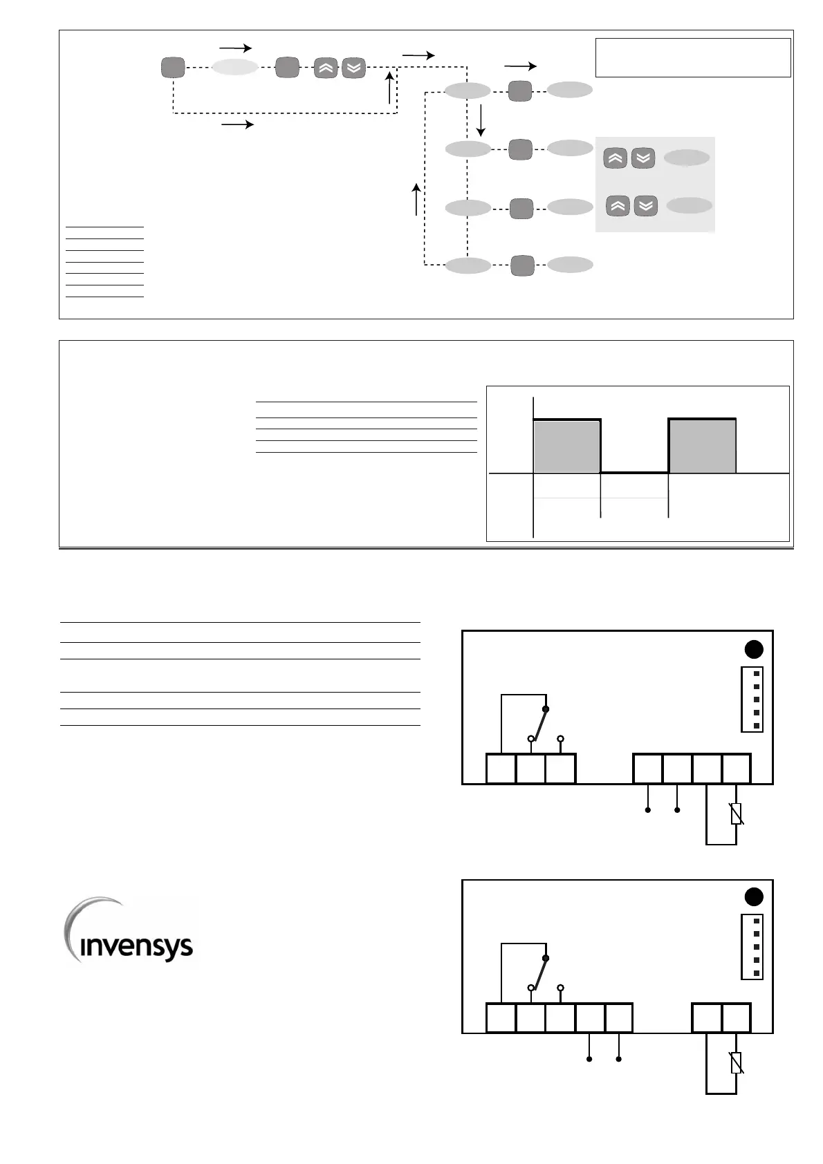
WIRING (12 and 230V)
1 - 2 N.C. regulator relay output OUT
1 - 3 N.O. regulator relay output OUT
6 - 7 Power supply • model 230V: 3 VA max.
• model 12V: 1,5 VA max.
8 - 9 Sensor input (thermostat) Pb1
A TTL input for Copy Card
PLEASE NOTE:
•User Default Settings
• for relay capacities check on the instrument label
In the diagram it is shown relays with 8(3) 1/2 hp 250V
capability and 12/230V supply
1 2 3
6 7 8 9
IC 901 - 12 V
A
Supply
Pb1
OUT
1 2 3 6 7
8 9
IC 901 - 230 V
A
Supply
Pb1
OUT
Invensys Controls Italy s.r.l
via dell'Industria, 15 Zona Industriale Paludi
32010 Pieve d'Alpago (BL) ITALY
Telephone +39 0437 986111
Facsimile +39 0437 989066
Internet http:/www.climate-eu.invensys.com
OFt
Off
On
OUT
Ont Ont
When the sensor detects an
error condition:
• the code E1 is displayed
• the regulator is activated as
indicated by the "On" and "Off"
parameters if programmed for
the duty cycle or:
Ont
0
0
>0
>0
OFt
0
>0
0
>0
Regulator output
OFF
OFF
ON
dc
Duty Cycle Diagram
CP
set
level 1 par
set
diS
CnF
Fpr
level 1 par
level 1 par
level 1 par
set
set
set
level 1
change
par value
scroll
parameters
set
PA1≠0
set
set PA1 value
press for 5 sec
Programming Menu Diagram
PARAMETERS
folders level 1
CP
diS
CnF
FPr