+V1
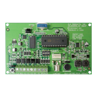
ELK-120 RECORDABLE VOICE AND SIREN MODULE
SW1
+12V NEG
R21
VOLUME INCREASE
JP1
MIC
PRG
ELK-120
PROGRAMMER
REC/EOM
MICROPHONE
RECORD
+B4+V2 +S3 SPEAKER-VS
SIRENVOICE
JP4
LINE OUT
ACTIVATE
CHANNELS
REPEAT
1SHOT
JP2
JP3
RECORDDISABLE
LED
REPEAT Continuously replays a channel while triggered
JP2
1SHOT
Plays a triggered channel only once.
NOTE: 1Shot is not available for pulsing input mode.
MIC Record using the on-board microphone
JP1
PRG Record using the optional ELK-129 sound interface
RECORD Enables the on-board record switch SW1
JP3
DISABLE Disables record switch, prevents accidental recordings
SIREN Sets +S3 & +B4 to be Yelp Siren & Horn channels
JP4
VOICE Sets +S3 & +B4 to be Recordable Voice channels 3 & 4
Jumper Settings
Line Level Output (RCA Jack)
for connecting to the input of a
paging system or audio amplifier
1234
Selects Channel
to be Recorded
Connects to
optional ELK-129
Siren with Voice Mode (JP4 = Siren)(for Alarm Applications)
+V1 = 0 to 8 Minute Recordable Message, see note
+V2 = 0 to 4 Minute Recordable Message
+S3 = Yelp Siren
+B4 = Temporal Coded Horn
Pulsing the +V1 input will play Voice 2 message
Pulsing the +S3 input will play the Temporal Coded Horn
-VS = Alternately plays Yelp Siren and Voice 1 message
Pulsing the -VS input will alternately play the Horn and Voice 2 message
Note: If Voice 1 (+V1) message recording exceeds 4 minutes, it will
overwrite Voice 2 (+V2) message space, thus +V2 becomes unusable
+S3 and +B4 together = Industrial Horn
Voice Only Mode (JP4 = Voice)
+V1 = 0 to 8 Minute Recordable Voice 1 Message, see note
+V2 = 0 to 6 Minute Recordable Voice 2 Message
+S3 = 0 to 4 Minute Recordable Voice 3 Message
+B4 = 0 to 2 Minute Recordable Voice 4 Message
Pulsing Mode is not available in Voice Mode
-VS = Alternately plays Voice 1 and Voice 3 messages
Note: If message recordings exceed 2 minutes they will overwrite the
next adjacent message, thus adjacent message becomes unusable
Summary of Connection Terminals & Switches
[+12V] If using a constant 12 Volt DC power source, connect the positive
side here. Nominal operating range of the ELK-120 v.2 is 11 to 14 Volts
DC. This input is only required if: A. The -VS negative trigger terminal is
used. B. Momentary activation of the channels is desired. C. The
activating source equipment is current limited to 30 mA or less.
[NEG] Connect to the negative side of the 12 Volt DC power source. Also
connect the negative from external trigger inputs here if they are from
another power source.
[+V1] Positive trigger input for Voice channel 1
[+V2] Positive trigger input for Voice channel 2
[+S3] Positive trigger input for Yelp Siren or Voice channel 3
[+B4] Positive trigger input for Temporal Coded Horn or Voice channel 4
NOTE: Channels may be combined to mix the output
[SPEAKER] Connect to 8 ohm speaker. (Max 4 Ohm load)
[-VS] Negative trigger input for controls with a switched negative output
R15
[Programmer (J1)] The optional ELK-129 Computer Sound Card
Interface module connects to this 5 pin connector to allow computer WAV
sound files to be downloaded into the ELK-120.
[Line Out (J2)] This RCA type connector provides line level sound output
for connection to Public Address amplifiers.
[Record Switch (SW1)] To record a message, set JP1 to MIC, activate
desired channel, press SW1, then speak your message into the on-board
microphone.
[Volume Control (R21)] Adjusts volume of the speaker output.
[Activate Channels] Selects channel to be recorded. Power must be
applied to the +12V and NEG terminals to use this switch.
Figure 1