Do you have a question about the Elka P 2500 and is the answer not in the manual?
General guidelines for safe operation and maintenance of the barrier, emphasizing adherence to regulations.
States copyright protection of the manual's content and restrictions on reproduction and utilization.
Documents purpose as installation instruction for partly completed machinery per directive 2006/42/EG.
Explains the meaning of warning symbols used in the manual to denote danger levels and remarks.
Emphasizes compliance with regulations, using original spare parts, and proper user instruction for safe operation.
Details safety rules for barrier operation, prohibiting children and untrained persons, and warning against reaching into moving parts.
Provides safety guidelines for using radio remote controls, stressing visibility and secure storage of transmitters.
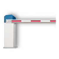
Defines intended use for passage control of vehicle paths and specifies usage classes, with warnings about improper use.
Highlights dangers from moving components, advising against touching them during operation and before maintenance.
Warns that unauthorized modifications can lead to hazards and interfere with the barrier's function.
Outlines necessary qualifications for personnel performing installation, maintenance, and repair work on the barrier.
Specifies the need to wear suitable personal protective equipment during installation, maintenance, repair, and dismantling.
Lists various CAUTION and WARNING notices related to potential injuries from specific hazards like crushing, falling objects, and sharp objects.
Instructs to inspect shipment for damage immediately upon receipt and report any issues to the manufacturer.
Lists the included components of the barrier system, detailing barrier model, boom, keys, and accessory box contents.
Provides guidelines for storing the barrier, including avoiding aggressive substances, heat sources, and specifying temperature ranges.
Offers safety warnings and best practices for lifting heavy barrier components, recommending suitable devices and safety shoes.
States that the machinery cannot be put into service until incorporated into a declared conforming final machinery.
Requires an EG-declaration of conformity for the complete system to be issued by the integrator after installation.
Informs that the barrier's name plate is located inside the front of the barrier housing.
Lists typical locations and interfaces for barrier applications, including parking garages and TCP/IP, RS485 inputs.
Provides key specifications like supply voltage, current consumption, temperature range, dimensions, and protection class.
Lists all necessary tools and equipment required for the installation of the barrier system.
Provides detailed diagrams and measurements for the correct mounting and placement of the barrier and its foundation.
Outlines basic requirements and considerations for preparing the foundation, including safety distances and concrete strength.
Explains the procedure for opening and closing the barrier's housing, including removing and installing the hood.
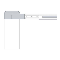
Details the process for attaching the boom connector to the main shaft and ensuring proper fit and alignment.
Describes how to convert the barrier for boom mounting on the left side, including hood removal and cap transfer.
Guides the installation of the barrier boom, including spring removal, mechanics positioning, and boom attachment to the connector.
Instructs on mounting and adjusting the balancing springs based on boom length and equipment, with specific spring types noted.
Details factory-set opening/closing times and explains how to adjust them via the controller's learning sequence.
Shows a diagram of the controller's interior, labeling key components like the controller board, supply voltage, and terminal rows.
Provides safety warnings and instructions for connecting the barrier to the mains power supply, emphasizing certified electricians.
Explains how to bridge or occupy terminal inputs for operation, such as for photoelectric barriers and boom missing contacts.
Presents schematic diagrams illustrating the electrical connections for the power supply, controller, and various components.
| Brand | Elka |
|---|---|
| Model | P 2500 |
| Category | Control Systems |
| Language | English |