EasyManua.ls Logo

Elma Instruments TDR-44 - User Manual

Elma Instruments TDR-44
11 pages
Print Icon
To Next Page IconTo Next Page
Loading...
CABLE FAULT
LOCATOR
Handheld Graphical
TDR
Model
TDR-44
Operation
Manual
Question and Answer IconNeed help?

Do you have a question about the Elma Instruments TDR-44 and is the answer not in the manual?

Summary

Introduction

Batteries

Safety Rules

Operating Instructions

Key Controls

Details the function of power, menu, backlight, up/down keys.

Fault Location Basics

General points for checking faulty cables and safety checks.

Fault Location Methods

Known PVF Location

Procedure for fault location on cables with known propagation velocity factor.

Unknown PVF Determination

Method to determine propagation velocity factor when it is not known.

Cable Fault Types

Short Circuits

Description of shorts between conductors and sheath shorts.

Open Circuits

Explanation of open conductors and open sheaths.

High Resistive Joints;Splices

Faults caused by poor connections or impedance transitions.

Splits

Analysis of untwisted pairs and their impact on fault traces.

Insulation and Water Ingress

Faults from moisture contamination and water at cable joints.

Bridge Tap

Identification of branch connections within a main cable pair.

Load Coils

Description of load coils and their reflection on TDR traces.

Specification

Technical Specifications

Details measure range, accuracy, impedance, display, and power supply.

Environment

Operating and storage temperature, and humidity limits.

Physical Characteristics

Information on case dimensions, material, weight, and leads.

Accessories

Repair and Servicing

Overview

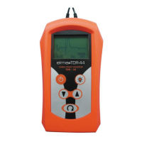
The Elma TDR-44 is a handheld graphical cable fault locator designed for identifying imperfections in metallic cables. It operates on a pulse-echo principle, transmitting a pulse into a cable and detecting reflections caused by faults such as open circuits, shorts, and bad connections. The device provides a visual representation of these reflections on its display, allowing users to pinpoint the location of faults.

Function Description:

The TDR-44 functions as a Time Domain Reflectometer (TDR), sending a pulse down a cable and measuring the time it takes for the reflection to return. The characteristics of the reflected pulse indicate the type and location of the fault. It can detect faults up to 3000 meters (9500 ft) away. The instrument's operation relies on the propagation velocity factor (PVF) of the cable's dielectric, which can be adjusted to suit various cable types. The device offers a "locate mode" where arrow keys are used to align a cursor with the fault's breakpoint on the trace, and the distance to the fault is then displayed in meters or feet.

Important Technical Specifications:

  • Measure Range: 100, 300, 1000, 3000m, and Auto range.
  • Accuracy: 0.9% of Range.
  • Resolution: 1% of range.
  • Gain: Auto Set across screen.
  • Output Pulse: 5V nominal in open circuit.
  • PVF (Propagation Velocity Factor): Variable from 0.01 to 0.99.
  • Output Impedance: 120 Ohm.
  • Pulse Width: Automatically varied.
  • Connectors: Two 4mm safety terminals.
  • LCD Display: 128x64 graphic LCD with backlight.
  • Display View Area: 44x62 mm.
  • Update Rate: Once per second.
  • No Touch Shutdown: 5 minutes (auto power-off if no key is depressed).
  • Power Supply: 6 AA alkaline or nickel-cadmium cells.
  • Battery Low Indicator: 6.5V nominal.
  • Operating Temperature: -20 to +60°C.
  • Storage Temperature: -30 to +70°C.
  • Humidity: 93%.
  • Case Dimensions: 210 X 100 X 50 mm.
  • Case Material: Fiberglass Nylon 6/6.
  • Weight: 550g (with batteries).
  • Leads: 2 meters safety plug and Alligator clip.

Usage Features:

The TDR-44 features a 128x64 pixel LCD graphics display with LED back-lighting, providing a clear visual trace of the reflected pulse. Key controls include:

  • Power On/Off Key: Switches the unit on and off. It also initiates the auto power-down feature after 5 minutes of inactivity.
  • Menu Select Key: Allows users to set parameters such as Propagation Velocity Factor (PVF), Cursor Control, Range select, and Measure unit (meters or feet).
  • Backlight Key: Illuminates the display backlight.
  • Up/Down Keys: These keys have multiple functions depending on the mode:
    • In PVF mode, they adjust the Propagation Velocity Factor.
    • In locate mode, they scroll the cursor left/right to align with the fault breakpoint. Holding the key down after two presses accelerates cursor movement.
    • In range mode, they scroll through the available ranges (100m, 300m, 1000m, 3000m, and auto-range).
    • They also toggle the measure unit between Metres and Feet when the appropriate menu is selected.

The instrument powers up in locate mode with a default range of 3000 meters and an optimum PVF for cable fault location. The auto-range feature automatically scrolls to the next range when a predetermined point on the display is reached.

The TDR-44 can identify various cable faults:

  • Short Circuits: Indicated by a downward polarity pulse. This includes shorts between conductors, sheath shorts (when a conductor contacts the metallic sheath), and crosses (conductors in different pairs crossing at a junction box).
  • Open Circuits: Indicated by an upward polarity pulse. This includes disconnected or broken conductors and open sheaths.
  • High Resistive Joints/Splices: Caused by poor connections, producing reflections similar to open conductors, with amplitude depending on joint quality. Transitions from low to high impedance cables can also cause similar reflections.
  • Splits: Occur when a cable pair is untwisted, typically at junction points. These cause an upward fault pulse (at the split) followed by a downward fault pulse (at the re-split).
  • Low Insulation and Water Ingress: These faults produce a reflection resembling a short conductor fault pulse where moisture begins, followed by a small open-type fault pulse where moisture ends. Gradual moisture increase broadens these pulses into a gentle shell or dip in the trace.
  • Low/Water at Cable Joint: Similar to low insulation, but specifically at cable joints contaminated by wet environments, resulting in a trace followed by a small, gradually decreasing sine or square wave.
  • Bridge Tap: Occurs when another pair of conductors branches off the main cable. This causes a short conductor downward reflection due to impedance sharing, followed by an upward reflection from the end of the tap.
  • Load Coils: Appear as open circuits to the TDR, resulting in an upward reflection.

Maintenance Features:

The TDR-44 is designed for ease of use and minimal user maintenance. The only user-serviceable item is the replacement of batteries. Instructions for battery replacement are provided:

  1. Unscrew the two screws securing the battery cover on the rear.
  2. Lift off the cover.
  3. Remove old batteries or insert new AA batteries, observing polarity markings.
  4. Replace the battery cover and secure the screws without over-tightening.

In the event of a failure beyond battery replacement, the instrument should be returned to the nearest distributor or manufacturer for repair. The manual emphasizes safety rules, particularly ensuring that the circuit under test is de-energized before connecting the fault locator. It also advises against using damaged leads, probes, or clips.

Elma Instruments TDR-44 Specifications

General IconGeneral
BrandElma Instruments
ModelTDR-44
CategoryCable Tester
LanguageEnglish