100-125A
200-250A
315-630A
A 210 332
387
A1 243 375 436
B 119 165 260
B1
107 134 222
C 168 240 285
E 125 154 220
G 172 172 172
J 228 348 406
K 86 109 180
L 6.5 6.5 9
N 89 100 103
P 30 50 65
R 15 24 40
S 34.7 30 50.5
T 2.4 3.5 5
U 107 134 222
8 11 13
Y 41 69 84
Y1 91 151 191
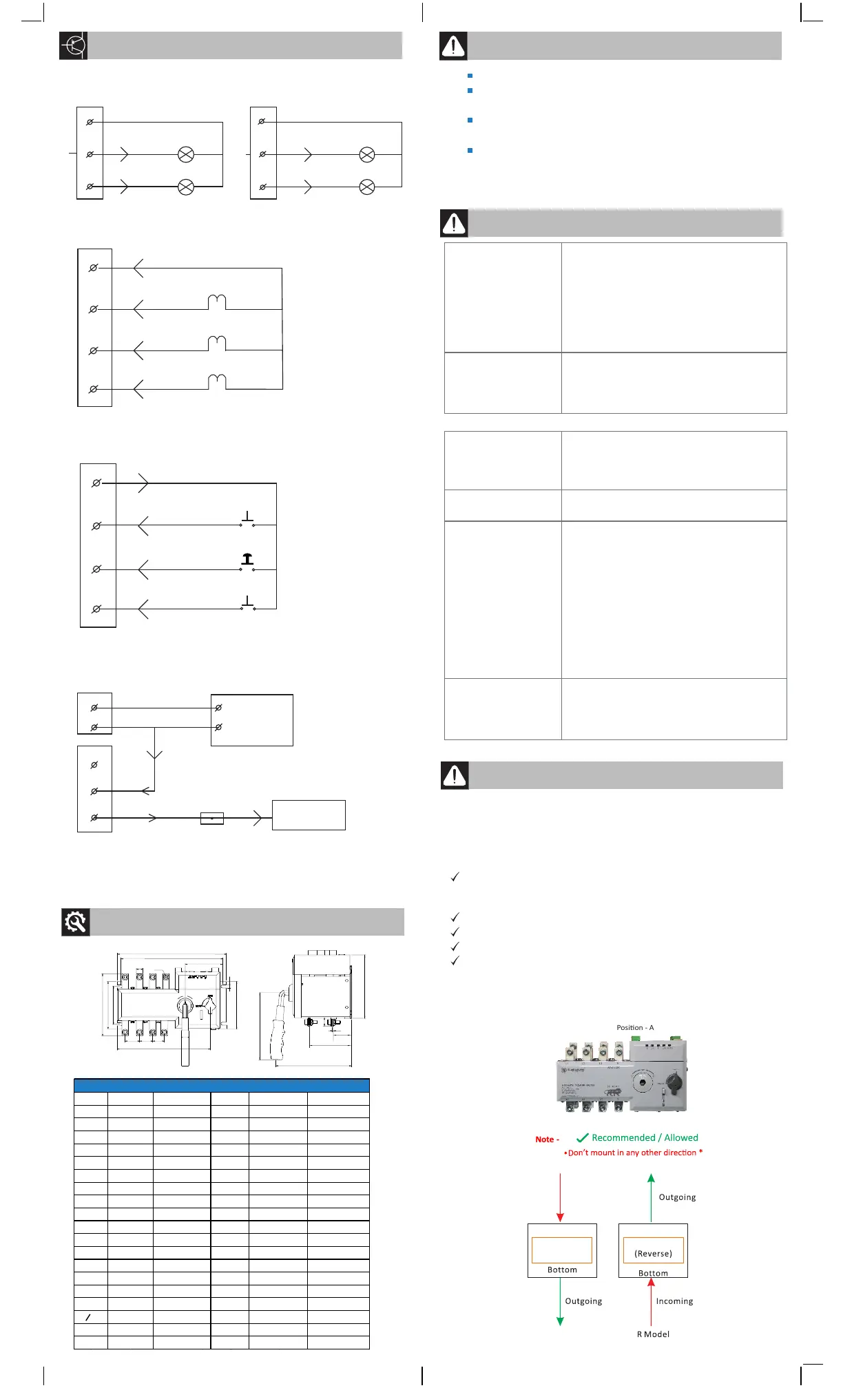
Overall Dimensions
Allow only professional to install, commissioning and maintenance.
Switch off the primary and secondary source before installaon,
commissioning and maintenance.
Mandatory use of a mulmeter to check to ensure power
is switched off.
The device must be reliably earthed as per requirement.
Reset the panel door and arc shield before powering the device.
An unauthorized operaon may result in electric shock,
fire or explosion.
9. PRECAUTIONARY MEASURES TO BE TAKEN
ATeS does not operate
electrically
1. Verify the Source I and Source II power
supply voltage and frequency healthiness.
2. Verify if the selector switch in the auto
posion
3. Verify the source healthiness LED (Red) is
ON
4. Verify the Source I and Source II Glass Fuse
5A Condion.
Manual operaon of
ATeS not possible
1. Verify if front selector switch is in manual
mode.
2. Make sure that the product is padlocked.
3. Verify the direcon of the handle.
Source availability
indicaon not blinking
1. Verify the Source I and Source II power \
supply voltage & frequency healthiness.
2. Verify the Glass Fuse 5A status, replace the
fuse if it is failed.
Fuse failure
1. Verify the control wiring ( short circuit or
wrong wiring )
DG does not start in
auto mode /
remote mode
1. Verify the DC auxiliary voltage ( should be
12-30 VDC )
2. Verify the batery system voltage, If any
fault in DG Controller.
3. Verify the (501-503) terminal connector.
4. Verify the selector switch is in posion in
auto.
5. Verify the generator control wiring.
6. 501- DG stop output
502 – common
503 – DG Start output
Source healthy
indicaon is flashing
1. This happens when ATeS mer is running or
the changeover.
2. Verify the Source healthy condion.
3. Verify if the Fire Linkage Fault is acve.
10. TROUBLESHOOTING GUIDELINES
11. WARRANTY INFORMATION
Warranty is provided by Elmeasure and covers defects in workmanship
and materials in your product. The Period of warranty is 12 months
from the date of Invoicing. The warranty claims that relate to defects
caused by any of the following factors are not covered by the
Contractual Warranty.
Improper use or Non-compliance with installaon, commissioning,
operaon or maintenance instrucons (i.e. not according to the
operaon & installaon manual).
Unauthorized modificaons, changes or aempted repairs.
Failure to observe applicable safety standards & regulaons.
Damages during transportaon or storage.
If the original idenficaon (trade-mark, serial number) markings have
been defaced, altered, or removed.
7. ATS CONTROLLER WIRING
Recommanded Cable for ATS-DG Controller
2.5 Sq.mm 4 Core Copper Cable•
Maximum Distance - 25 Mtrs•
Generator Controller wiring should be done by Generator Manufacturing •
Company
8. MECHANICAL DIMENSION
J
A1
N
L
K
U
B
R
P P
P
A
O
X
B1
C
G
E
T
S
Y
Y1
ATeS Mounng orientaon
Posion - A
Incoming
TOP TOP
ATeS ATeS R
C Model
( C )
401
402
403
404
R Phase
Y Phase
B Phase
S1
S1
S1
S2
Don't Connect more than 100mA Input to CT terminal (401 , 402, 403, 404)
Note:-
+VE
-VE
DG Batery
12 V / 24 V DC
301
302
Auxiliary Input
DG START/STOP LOGIC
501
Common I/P
503
DG Controller
(Remote Start
Digital Input(-ve)
2 A Glass Fuse
502
Not Use
DG Start/output
12/24 DC Supply is not
Mandatory
Note:-
EB STATUS CONTROL WIRING
DG STATUS CONTROL WIRING
101
102
103
N
L1
L2
EB Healthy Indicaon (230 V AC)
EB Load on Indicaon (230 V AC)
EB INDICATION OUTPUT
N
203
DG Healthy Indicaon (230 V AC)
202
L3
DG Load on Indicaon (230 V AC)
L4
201
DG INDICATION OUTPUT
Note:-
Don't give a any input supply to 101 ,102 , 103, 201, 202, 203. All are 230 V AC
Output for status indicaon.
Don't connect any input supply to 601, 602,603, 604.
Note:-
REMOTE CONTROL WIRING
Common Supply from ATeS
601
602
603
604
Source 1 - ON
Trip
Source 2 - ON
Remote control ( Selector Switch/ PLC/SCADA)
CURRENT SENSING LOGIC WIRING
160A
40-63A
195
226
117
107
190
126
175
215
87
7
81
25
12
18
2
107
6
43
94
X
0
200
302
135
127
204
136
200.5
287
101
8
100
36
20
23.5
3.5
126.5
10
69
151
 Loading...