Do you have a question about the Elmo Gold Solo Double Twitter Series and is the answer not in the manual?
Explains the structure of product catalog numbers for the servo drive.
Outlines the guide's scope, focusing on technical data and connectivity.
Crucial warnings for safe installation, operation, and handling.
Essential cautions to prevent damage and ensure proper procedures.
Details the product warranty terms and conditions.
High-level description of the servo drive's capabilities and features.
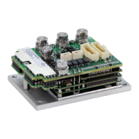
Dimensions, weight, and mounting method of the drive.
Electrical and performance data for D-type models.
Input voltage range (VL) for the control supply.
Key features including STO, I/O, and communication options.
Operating temperature, humidity, altitude, shock, and vibration limits.
Relevant functional safety standards for STO.
Standards for adjustable speed drives and electrical safety.
EC Declaration, environmental testing, and EMC compliance details.
Confirmation of EtherCAT protocol compliance.
Quality, reliability, workmanship, and environmental regulations compliance.
Procedures for unpacking and identifying the servo drive.
Steps for attaching the drive to a heat sink for thermal management.
Introduces diagrams for CAN and EtherCAT network connections.
Explanation of wiring symbols used in diagrams.
Identification of connectors and their placement on the drive.
Recommended mating connectors, wires, and crimping.
Guidance on connecting logic, control, and communication signals.
Instructions for inserting wires into the drive's female connectors.
Instructions for connecting power supplies and motor wires.
Description of the dual-color LED for status indication.
Pin assignments and functions for the J10 connector.
Details for connecting Port A feedback devices (encoders, Hall sensors).
Details for connecting Port B feedback devices (encoders, resolver).
Details for the Port C emulated encoder output.
Pin assignments for J11 connector (Digital I/O, STO, Analog, RS-232, USB).
Configuration details for digital inputs (Source/Sink PLC, 5V Logic).
Configuration details for digital outputs (Source/Sink PLC, 5V Logic).
Connection details for the Safe Torque Off input.
Details for connecting analog input signals.
Connection details for the RS-232 interface.
Connection details for USB communication (EtherCAT version).
Information on EtherCAT IN/OUT connectors and setup.
Explanation of EtherCAT status and link LEDs.
Information on CAN IN/OUT connectors and interface.
Diagrams and notes on CAN network topology.
Steps for initializing the drive using Elmo Application Studio.
Guidance on managing drive heat dissipation and thermal limits.
Graphs showing power dissipation versus motor current.
Guide on interpreting charts and selecting heat sinks.
Technical drawings of the drive's physical dimensions for EtherCAT.
Technical drawings of the drive's physical dimensions for CAN.
List of available power, EtherCAT, and CAN cable kits.
Information on necessary tools and components for wiring.