Art.-Nr./Art. No./Réf./N° art/N° art.: 9010008B01M Version: 1.3 Date: 29.08.2017 1/9
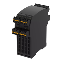
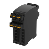
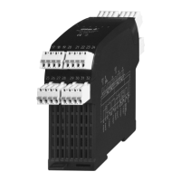
Safety control unit eloFlex 471EFR
Translation of the original operating instructions
Table of contents
1 About these operating instructions .......................................................1
2
Designated use.....................................................................................1
3
Approvals..............................................................................................1
4
Safety information.................................................................................1
5
Warning against misuse .......................................................................1
6
Exclusion of liability ..............................................................................2
7
Function................................................................................................2
8
Technical s
pecifications........................................................................2
9
Installation ............................................................................................2
10
Electrical connection.............................................................................3
11
Commiss
ioning.....................................................................................3
12
Maintenance.........................................................................................3
13 Troubleshooting....................................................................................3
14 Disposal................................................................................................3
Declaration of conformity ................................................................................9
GB
1 About these operating instructions
The following eloFlex standard models are described:
- 471EFR2D14K_ SIL2/PLd with 4 safety outputs
- 471EFR3E14K_ SIL3/PLe with 4 safety outputs
- 471EFR3E13K_ SIL3/PLe with 3 safety outputs
- 471EFR3E12K_ SIL3/PLe with 2 safety outputs
- 471EFR3E11K_ SIL3/PLe with 1 safety output
Refer to the data sheet for the chosen configuration.
Data sheets can also be requested from elobau for customer-specific safety
control units. The information specified in the data sheet applies for customer-
specific models if this information deviates from the operating instructions.
The person installing the safety control unit must be provided with the operat-
ing instructions.
The operating instructions and data sheet must be kept in a legible condition
and in an accessible location.
Meaning of the symbols used:
Warning
Failure to observe this warning may result in faults or malfunc-
tions.
Failure to observe this warning may result in personal injury
and/or damage to the machine.
Information
Indicates available accessories and useful additional informa-
tion.
2 Designated use
The safety control unit is part of the overall system or machine and is for the
purpose of assuming safety-related functions.
This is done by monitoring signals, for example safety sensors, emergency-
stop buttons, position switches, no-contact protective equipment (BWS). The
product must be used only in accordance with the descriptions below.
3 Approvals
[
AUXILIARY DEVICE]
E334998
4 Safety information
- Ensure that the safety control unit is installed and put into oper-
ation only by specially trained, authorized personnel.
- Only install and put the device into operation once you have
read and understood the operating instructions and are familiar
with the applicable regulations on occupational safety and acci-
dent prevention.
- Ensure that the corresponding fuses (see "Technical specifica-
tions") are used. Never bypass or repair any fuses.
- Ensure that the safety control unit is only used to protect against
dangers.
- Ensure that all applicable safety requirements for the machine in
question are observed.
- Ensure that all applicable European directives and national
laws/directives are observed.
-
-
Ensure that the control output is only used for displaying the op-
erational status of the safety control unit.
There are no known residual risks, if all of the information con-
tained in these operating instructions is co
mplied with.
5 Warning against misuse
- In case of improper or unintended use or manipulation, dangers
for personnel and damage to the machine or system compo-
nents cannot be excluded by the use of the safety control unit.
Please also observe the relevant information stipulated
ISO 14119.
- Make sure that no current or voltage peaks that are higher than
the electrical specifications of the safety control unit are caused
by any external components. Current or voltage peaks are pro-
duced, for example, by capacitive or inductive loads.
- Exceeding the electrical specifications of the safety control unit
(e.g. in the event of defective wiring or short circuits) can
damage the system irreparably. Non-compliance may result in
reduced service life.