Do you have a question about the ELPRO ECOLOG-PRO Series and is the answer not in the manual?
General disclaimer of liability for product use and installation.
Details warranty periods and conditions for ELPRO-BUCHS AG products.
Specifies guarantee conditions for software products and manuals.
Outlines guarantee coverage for hardware components and third-party products.
States that company and product names are protected property.
Explains informational icons and important warning messages.
Defines syntax for placeholders and software-specific codes.
Indicates product compliance with CE marking and relevant EMC guidelines.
Lists FCC ID and IC for compliance with radio frequency regulations.
Specifies disposal requirements according to WEEE directive.
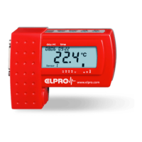
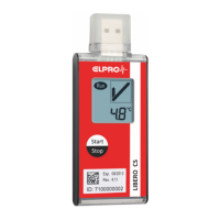
Introduces the LBR, 4PT, 4MA, 4DI, and 4DO modules and their functions.
Defines the minimum system configuration for ECOLOG-PRO.
Provides notes on module installation and operation.
Explains how configuration and monitoring are performed using elproMONITOR software.
Covers power supply unit usage, cleaning, and environmental operating conditions.
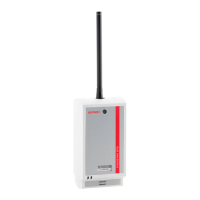
Describes the LBR module's roles in power supply, network connectivity, and its ID number.
Explains the meaning of status indicator lights for module activity and Ethernet status.
Lists power supply, connection, and network standards for the LBR module.
Illustrates the circuit diagram for the LBR module's power supply unit.
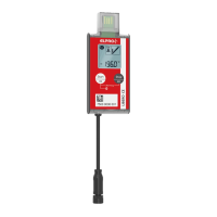
Describes the 4PT module for Pt100 sensors, connection, and status indicators.
Details measurement range, accuracy, resolution, and cable fault compensation.
Explains logging intervals, data security, and calibration data storage.
Shows connection cables for M12 sensors and the Pt100 4-wire circuit diagram.
Explains the meaning of different sensor status indicators for the 4PT module.
Describes the 4MA module for 4-20 mA transmitters and its status indicators.
Lists measurement range, transmitter power, load, accuracy, and cable length.
Details logging intervals, data security, and circuit diagrams for 4-20 mA transmitters.
Explains the meaning of different sensor status indicators for the 4MA module.
Describes the 4DI module for logging statuses from contact inputs.
Details contact input types, voltage, current limits, and connection cable length.
Explains logging intervals, pulse length, and data security for the 4DI module.
Explains contact data detection and provides circuit diagrams for sensors.
Describes the 4DO module for alarm forwarding using contact outputs.
Details contact output type, external power, switching current, and cable length.
Explains parameterization of threshold values and alarm delay times.
Details pin assignments and operating states for contact outputs.
Explains power/ground for indicators and how local alarms are triggered.
Explains alarm forwarding and wire break monitoring.
Describes the function and types of the plug-in power supply unit.
Lists input voltage, output voltage/current, dimensions, and cable length.
Shows maximum current draw for each ECOLOG-PRO module type.
Outlines prerequisites for configuring the ECOLOG-PRO LBR and the overall process.
Describes how to find the LBR using its Ethernet address.
Explains how to define the LBR by entering its IP address.
Describes how to define the LBR by entering its hostname.
Covers entering or adapting network parameters in the configuration window.
Lists part numbers, designations, and descriptions for accessories.
Tracks changes made to the document with author, date, version, and description.
| Brand | ELPRO |
|---|---|
| Model | ECOLOG-PRO Series |
| Category | Data Loggers |
| Language | English |