0
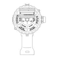
CONTROLLER
TEMPERATURE
Ex-TC/A
LOW
ALARM
LED
x1
x10
x100
0
0
Ex ib
PE1
230 VAC
20A 55°C
25A 40°C
PE1
L
N
N0
L0
PE2+3
250 VAC 3A
24 VDCA 5A
PE3
PE2
PE1
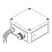
CONTROLLER
TEMPERATURE
Ex-TC/AL
LOW
ALARM
LED
x1
x10
x100
0
0
0
PE1
230 VAC
20A 55°C
25A 40°C
PE1
L
N
N0
L0
PE2+3
250 VAC 3A
24 VDCA 5A
0
0
0
LIMITER
TEMPERATURE
HIGH
ALARM/
RESET
0
CONTROLLER
TEMPERATURE
Ex-TC/M
LOW
ALARM
LED
x1
x10
x100
0
0
Ex ib
PE1
230 VAC
20A 55°C
25A 40°C
PE1
GND
D-
D+
L
N
N0
L0
PE2+3
11
www.eltherm.com
11
www.eltherm.com
• De-energize the circuit again and
connect all signal and sensor lines as well as the heating
cables to the corresponding terminals
• Tighten the terminals nger-tight (torque between 0.6
and 0.8 Nm)
• Tighten unused terminals as well
• Push the controller back into the lower position of the
slotted holes and tighten the retaining screws (see fol-
lowing page “INSTALLING THE CONTROLLER” page 11).
• Close all openings (covers, threaded holes, cable entries).
Take into account the torques in the
“TECHNICAL DATA” section.
• Tightening the cable entries too tightly can adversely
aect the IP protection type!
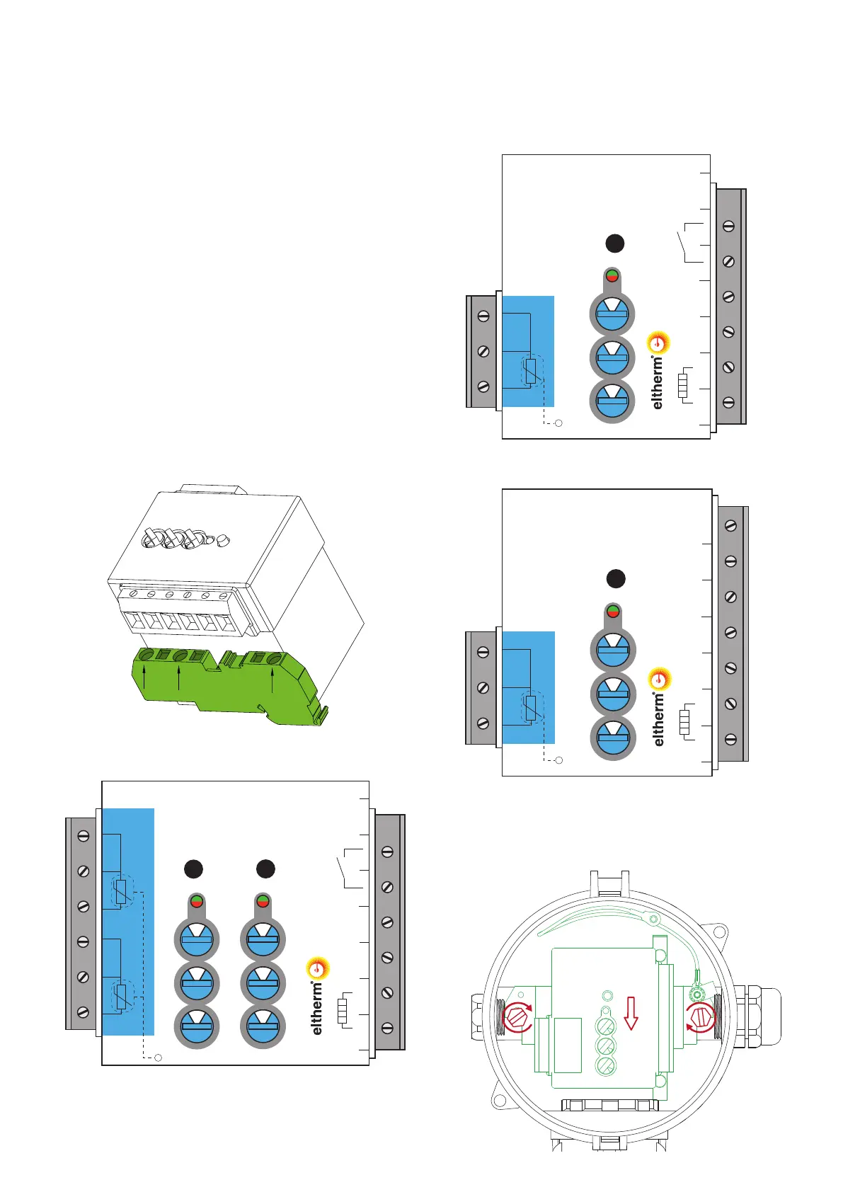
CONNECTING THE CONTROLLER
PE TERMINALS (for all Ex-TC devices)
Ex-TC/AL-It
Ex-TC/A-It
Ex-TC/M-It
INSTALLING THE CONTROLLER
1 Slide controller into the locking mechanism. Tighten
retaining screws. Move the cable into its nal position and
tighten the cable glands
 Loading...