User Manual QT series generation 2.5, ID 2021, rev 3.2, January 14, 2022
Note! For all available parameters, see System Integrators Manual CANopen
Interface.
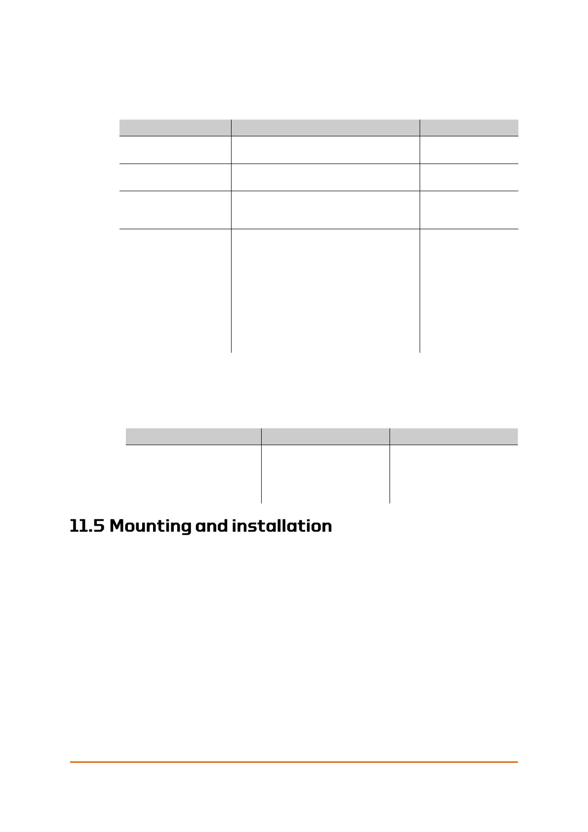
Table 12: Failsafe triggers
Set Failsafe from
IAS/E3C
Manually setting Failsafe for test or
other scenarios
Initiate Failsafe protocol if the signal
is lost after the predefined time delay.
Initiate the failsafe protocol if external
power is below critical after the
predefined time delay.
UPS Error Timeout
triggered by one or
more of the following
− UPSCOMERR
− TEMPERR
− SOHERR
− SOCERR
The UPS Error Timeout is a common
timer for all internal errors before
triggering of the failsafe protocol.
− PSU Communication error
− Temperature above critical
− State of Health below
minimum
− State of Charge below
minimum
Disabled (65535)
or adjustable
between 0-65534
seconds
Table 13: Other important configurable parameters
Timer for ensuring that
the heartbeat is present
for the requested time
period before reporting
all OK to IAS
The Failsafe actuator is mounted and installed in the same way as a
standard actuator, with the following exceptions:
• There are routines to follow for the storage and installation caused by
battery considerations, see information in section 11.3.2 on page 65.
• There are considerations to make when you open the actuator, see
11.5.2 below.
• The interface communication box is fastened to the failsafe module with
nuts instead of screws.
• Connection of the battery cable sees 11.8.2 on page 74, steps 12 – 16.
See Chapter 4 Mounting and Installation on page 34 on how to connect the
external power and signal cables to the communication interface unit.
 Loading...