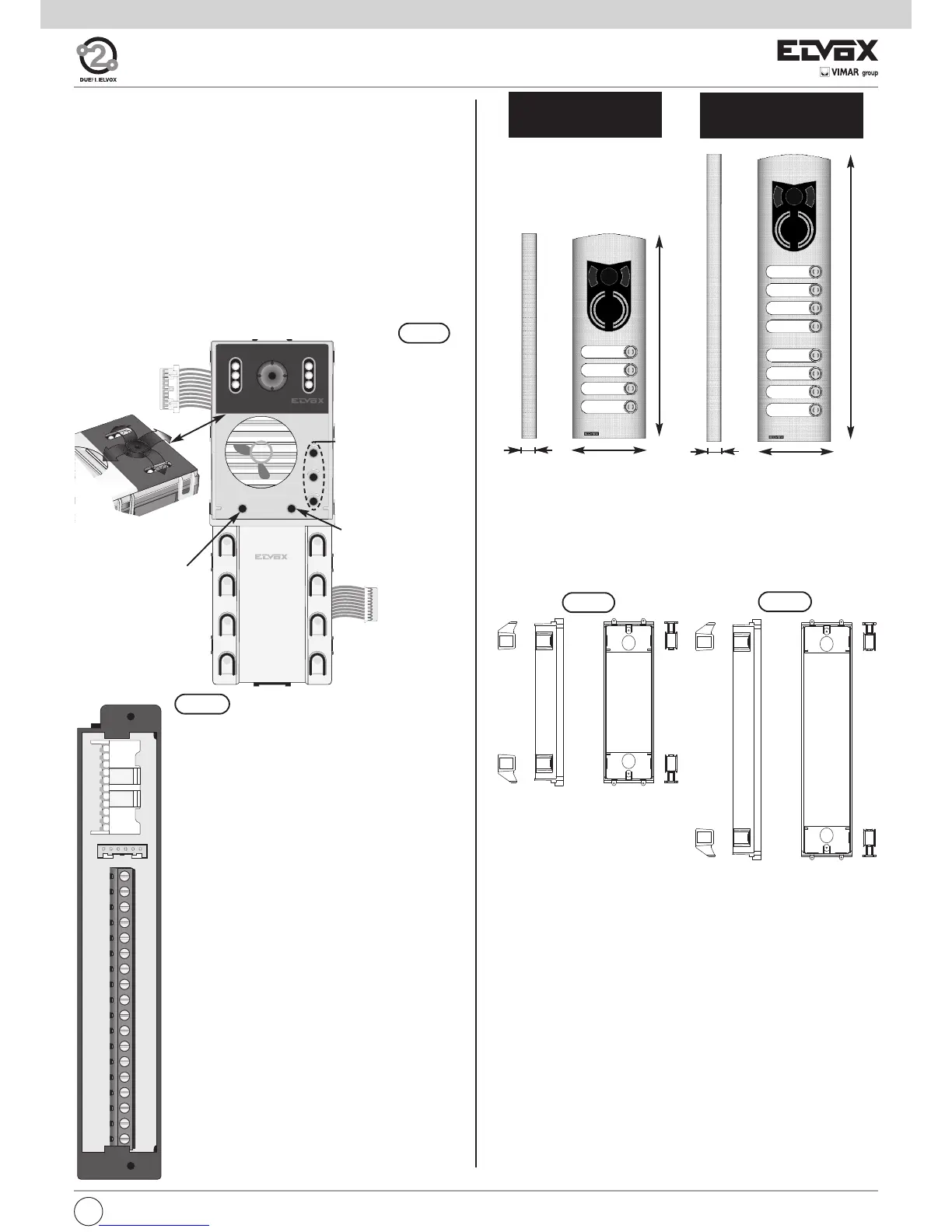
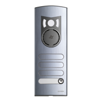
STANDARD MODULES
The standard modules consist of: an electronic unit and a connection ter-
minal block. The electronic unit is equipped with a speech unit, camera (on
video versions), wiring for terminal block connections, wiring for connec-
tion of additional modules and 8 call push-buttons, 6 of which are used for
standard programming.
The standard electronic units for colour video panels are equipped with a
camera with the following specifications:
- CCD 1/4" color sensor
- Resolution: 350 linee TV
- Aspheric lens f = 2.7 mm, F = 2.4
- Minimum lighting level 1.0 lux
All cameras can be tilted manually, horizontally and vertically, on removal
of the entrance panel external plate.
Example of standard module with camera.
3
2
1
RST
PRG
4
START
SI / YES
5
STOP
NO
6
FINE
END
1
PREC.
PREV
2
SUCC.
NEXT
3
OK
PRG
CN1) Connector for electronic unit.
CN2) Connector for programmer type 950C.
B2) 2-wire Bus (cable riser).
B1) 2-wire Bus (cable riser).
EXT+) External power supply (+ type 6923).
EXT-) External power supply (- type 6923).
VLED) LED power supply for additional modules.
X) Video input (coaxial core), for external ca-
mera (for type 89F8 only).
M) Video input (coaxial sheath), for external ca-
mera (for type 89F8 only).
PA) Input for door open sensor (with reference to
terminal M).
CA) Door open control (with reference to termi-
nal M).
M) Ground.
S+) 12Vdc lock output (+).
S-) 12Vdc lock output (-).
+12V) +12V output (max 100 mA) with PTC protec-
tion.
-L) External camera pilot, open collector output.
SR) Lock pilot via relay, open collector output.
F2) F2 function pilot via relay, open collector out-
put.
F1) F1 function pilot via relay, open collector out-
put.
M) Ground.
B2
B1
EXT+
EXT-
VLED
M
PA
CA
M
S+
S-
+12V
-L
SR
F2
F1
M
X
B2
B1
EXT+
EXT-
VLED
M
PA
CA
M
S+
S-
+12V
-L
SR
F2
F1
M
X
CN2
CN1
CS2411 250105
Wiring for ter-
minal block
connection
Wiring for con-
nection of addi-
tional modules
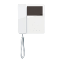
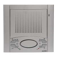
Controls:
1 - Balance
2 - External volume
3 - Internal volume
Manual horizontal
and vertical tilt
Fig. 3
Reset
)
*
Electronic unit
Fig. 4
Fig. 5
Terminal block
*
The panel supplies a current peak IT> 1A for 10
mS, followed by a hold current I
M
= 200mA for the
entire duration of the lock control (see lock time).
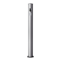
HEIGHT OF 2-MODULE
ENTRANCE PANELS
HEIGHT OF 3-MODULE
ENTRANCE PANELS
Box width 88mm for 1 horizontal module and 50 mm depth.
Type 9092, 9192
For 2 additional modules.
Height: 2 verical modules (248 mm)
Type 9093, 9193
For 3 additional modules.
Height: 3 vertical modules (360 mm)
ACCESSORIES: FLUSH-MOUNTED BACK BOXES
396
100
282
22
100
22
Fig. 2
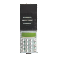
GB
3