FLUSH-MOUNTED ENTRANCE PANEL INSTALLATION WITH RAIN-
PROOF COVERS.
Assembly of flush-mounted entrance panel requires the use of the flush-
mounted back boxes type 9092 (9192), 9093 (9193) respectively for 2 or
3 electronic modules mounted vertically (Fig. 4 and 5).
If the entrance panel uses more than one flush-mounted back box, the
rainproof covers must also be used (see push-button plates: accessories
on page 4, series 1Pxx), according to the number of modules fitted verti-
cally or horizontally.
Note: Back boxes type 9092 and 9192 or 9093 and 9193 cannot be mat-
ched between them but only between: 9092 with 9092, 9192 with 9192 or
9093 with 9093 and 9193 with 9193.
Warning:during installation of back box type9192 it is necessary to insert
the cover sup-plied in order to avoid possible deformationsof the box itself.
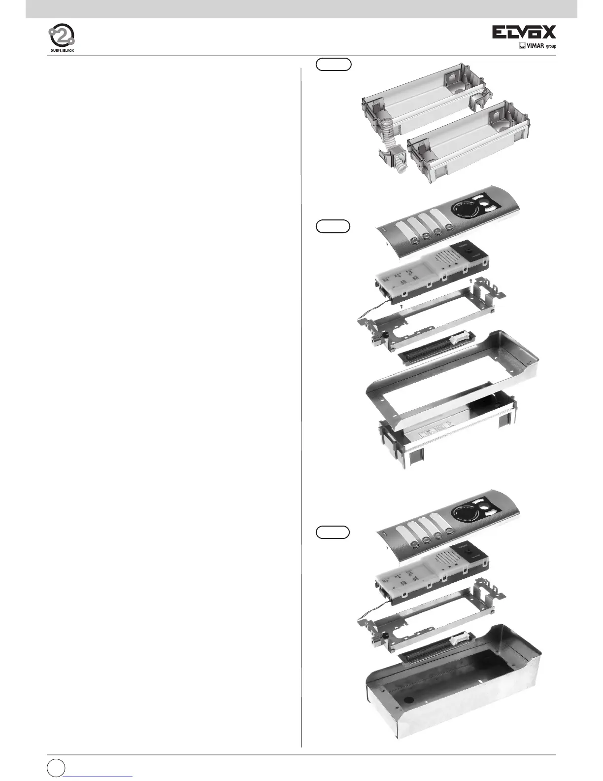
Installation:
- If the installation requires a combination of several back boxes, use the
hooks supplied with the back boxes to secure them together (Fig. 6).
- Install the back box with the upper edge at a height of approx. 1,65 m
from the ground (Fig. 1).
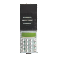
- Fix the terminal block of the electronic unit under the module holder frame
by means of the screws supplied (Fig. 7).
- Fix the rainproof cover to the flush-mounted back box using the screws
supplied (Fig. 7).
- Fix the module holder frames to the frames and the back boxes (Fig. 7).
- Connect the terminal box of the electronic unit to the system.
- Connect the electronic unit to the terminal block by means of the wiring
on the upper section
(Fig. 2).
- Connect the additional entrance panels (Fig. 11), if any.
The connection of more additional modules may require an additio-
nal power supply Type 6582 for the LED supply voltage.
- Insert the electronic unit and the additional modules in the module hol-
der frames. Use the separator supplied with the additional modules to
keep them joined (Fig. 12).
- Insert the microphone in the lower right section of the module holder
frame (Fig. 9 - part. 1).
Pay attention that the microphone cables are inserted in the external
slot of the electronic module (Fig. 9A, 9B).
- If necessary, remove the white cover of push-buttons, of the electronic
unit and of the additional modules.
- Perform the programming phases.
- Reinsert the push-button protection.
- Close the entrance panel, attaching the plate first from the upper sec-
tion and then securing the lower section by means of the special key on
the head section.
- To remove the name-tag: Press lightly with the fingers to remove the
name-tag placed on the rear section of the push-button plate (Fig. 10).
SURFACE WALL-MOUNTED ENTRANCE PANEL INSTALLATION
Assembly of the surface wall-mounted entrance panel requires the use
of the back boxes series 1Exx.
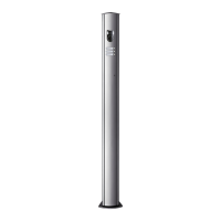
Installation:
- Fix the electronic unit terminal block under the module holder frame
by using the screw provided (Fig. 8).
- Fix the module holder frames to the frames and back boxes (Fig. 8).
- Connect the terminal block of the electronic unit to the system.
- Connect the electronic unit to the terminal block by means of the
cable present on the upper section (Fig. 2).
- Connect the additional modules, if any (Fig. 11).
The connection of more additional modules may require an addi-
tional power supply Type 6582 for the LED supply voltage.
- Insert the electronic unit and the additional modules in the module
holder frames. Use the separator supplied with the additional modu-
les to keep them joined (Fig. 12).
- Insert the microphone in the right lower side of the module holder
frame (Fig. 9 - part. 1).
Pay attention that the microphone cables are inserted in the external
slot of the electronic module (Fig. 9A, 9B).
- If necessary, remove the white cover of push-buttons, of the electro-
nic unit and of the additional modules.
- Perform the programming phases.
- Reinsert the push-button protection.
- Insert the module plates in the modules holder frames (Fig. 8).
- Close the entrance panel, attaching the plate first from the upper sec-
tion and then securing the lower section by means of the special key
on the head section.
- To remove the name-tag: Press lightly with the fingers to remove the
name-tag placed on the rear section of the push-button plate (Fig.
10).
Fig. 6
Fig. 7
Fig. 8
7
GB