16
GB
A
C
B
Fig. 3.7
B
A
A
A
Fig. 3.6
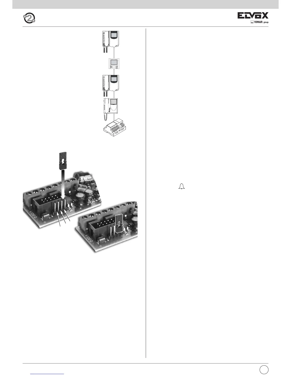
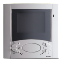
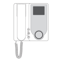
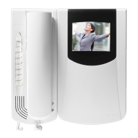
VIDEO SIGNAL STABILISATION
Inside the interphone there are some connec-
tors (A-B-C) and some jumpers for the video si-
gnal stabilization.
This jumper must be used in video installations
with several appliances (interphones and moni-
tors) connected in series (Fig. 3.6).
In series configuration displace the jumper
(only in the last set) into “B” position and keep
the jumpers of other interphones/monitors in
the initial position, i.e. “A”. (Fig. 3.6).
For other wiring configurations see note: "Bus
termination for ELVOX TWO-WIRE installations"
provided (Page. 44).
PROGRAMMING
There are three interphone programming modes: assignment of an iden-
tification code or call code (indispensable), assignment of a secondary
identification code (for interphones associated with a master interphone),
programming of pushbuttons for auxiliary services and intercommunica-
ting calls (when necessary).
Programming must be performed with the system switched on, without
active communication and only after connecting the interphones/monitors
to the system and programming the panels.
Identification code programming
The identification code is programmed via an entrance panel (MASTER),
already configured and present on the system.
The interphone is supplied without associated identification code. To ve-
rify this condition, press the lock release pushbutton and the interphone
should emit a triple “Beep”.
Attention: during the interphone/video interphone identification code
programming you have 30 seconds from the moment you enter the
programming in the interphone/video interphone and the moment
you press the call push-button on the panel or you send the code.
Programming phase:
1) Remove the interphone cover.
2) Press and hold the RESET pushbutton on the interphone.
3) Press and hold the tab on the lock release pushbutton, together with
the RESET pushbutton.
4) Release the RESET pushbutton, keeping the lock release pushbutton
pressed.
5) After 2 seconds the interphone emits a high tone and communication
is enabled with the panel. If the monitor is also connected to the inter-
phone, it is switched on and connected to the camera of the entrance
panel.
6) Release the tab of the lock release pushbutton.
7) On pushbutton entrance panels, press the call button for the inter-
phone, while on alphanumeric keypads, enter the call code and press
pushbutton “ ”.
8) If the system contains an interphone that already has the same asso-
ciated identification code, the panel emits a low signal and the opera-
tion should be repeated from point 2.
9) Otherwise the code is associated with the interphone and communi-
cation is terminated.