42
GB
5) Release buttons A and C.
Important: you will have 5 s in which to press buttons A and C (as indica-
ted in step 4). If button A and C is not pressed within the 5 s, steps 1, 2 and
3 must be repeated.
6) At this point, communication between the interphone and the entrance
panel begins and you have 25 s to link the ID code of the outdoor en-
trance panel:
- if using an alphanumeric entrance panel, enter the ID code (the same
primary ID code as assigned to the group master interphone) and con-
firm with the “bell” button.
- if using an entrance panel with buttons, press the button you want to
use for calling the interphone (the same button with which the group
master interphone was programmed).
Important: If the procedure described is not completed within the 25 s, it
must be repeated from step 1.
Important: When programming the primary and secondary ID, the inter-
phones undergoing programming automatically acquire a code that de-
pends on the association with the button or code used to call the outdoor
entrance panel. Correspondence between the primary ID and the respec-
tive secondary ID codes is provided in the table below.
Example: If ID = 8 is given to a second interphone, the automatic second
interphone identification attribution procedure will automatically assume ID
= 72 (see table).
When a call is made to ID = 8, both interphones will chime and you will be
able to answer from both. If, on the other hand, you enter 72 (the ID auto-
matically assigned by the procedure), a ring tone is emitted by - and you will
only be able to answer from - the interphone for which the secondary ID as-
signation procedure was carried out.
Manual programming
Basic interphone programming is as follows:
- ID programming, performed on the interphone receiving the call sepa-
rately or on the first in a group of interphones with simultaneous calls
(master interphone for the group).
- Secondary ID programming, performed for interphones linked to a
group master interphone/monitor.
- Programming programmable buttons or changing the default settings
of additional buttons, for auxiliary services or intercommunicating calls.
ID programming
To program the ID, proceed as follows:
1) Press and hold button B.
2) Press and hold button A at the same time.
3) Release the buttons when the red LED flashes.
4) Press and hold button C until you hear a “note” from the interphone to
confirm programming is underway; this will be accompanied by the red
LED lighting up steadily.
5) Release button C.
Important: you will have 5 s in which to press button C (as indicated in step
4). If button C is not pressed within the 5 s, steps 1, 2 and 3 must be repea-
ted.
6) At this point, communication between the interphone and the entrance
panel begins and you have 25 s to link the ID code of the outdoor en-
trance panel:
- if using an alphanumeric entrance panel, enter the primary ID code and
confirm with the “bell” button.
- if using an entrance panel with buttons, press the button you want to
use for calling the interphone.
Important: If the procedure described is not completed within the 25 s, it
must be repeated from step 1.
Important: If the installation already contains an interphone/monitor with
the same associated identification code, the entrance panel emits a low
sound signal and the process must be repeated from the start in order to as-
sign a different code.
Secondary ID programming
To program the secondary ID, proceed as follows:
1) Press and hold button B.
2) Press and hold button A at the same time.
3) Release the buttons when the RED LED flashes.
4) Press and hold buttons A and C until you hear a “note” from the inter-
phone to confirm programming is underway; this will be accompanied by
the RED LED lighting up steadily.
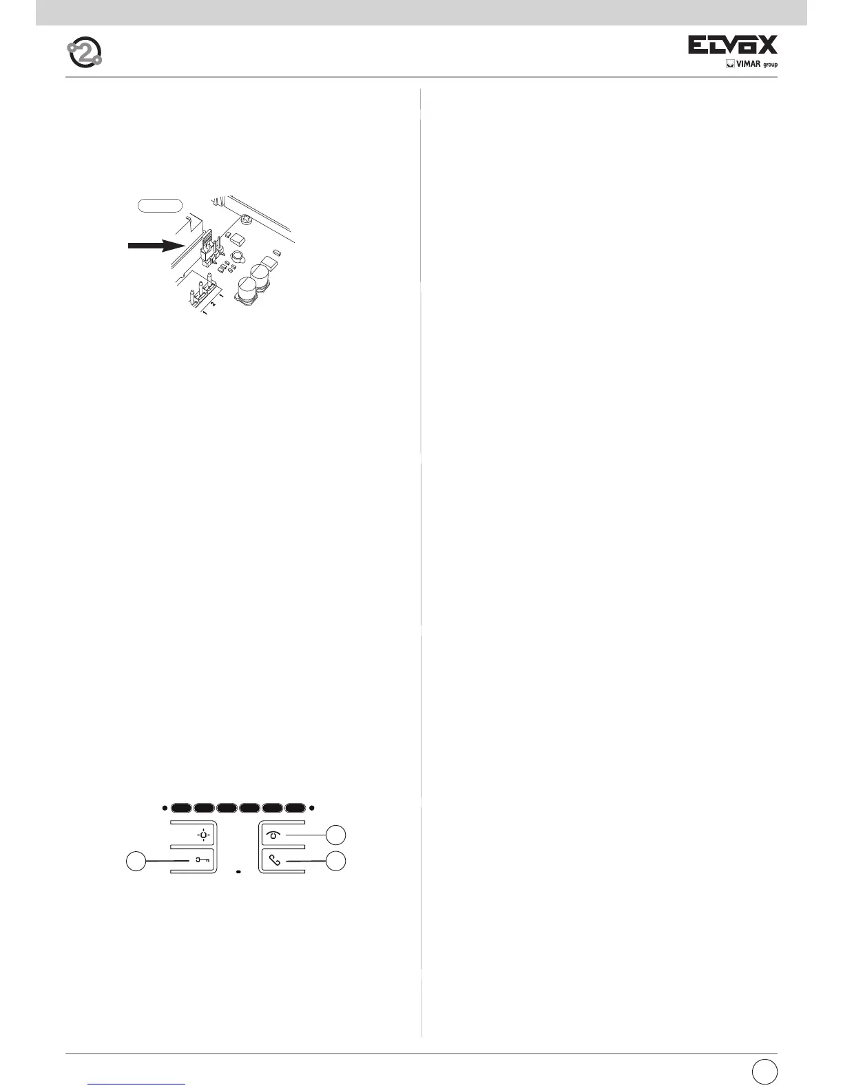
A
B
C
Fig. 6
Bus termination for video signal stabilisation
There is a “BUS termination connector” (A-B-C) inside the interphone to
stabilise the video signal.
Depending on the wiring configuration (interphones/monitors connected in
series or which are distributor extensions), set connector ABC to jumper, as
described in note “Bus termination for ELVOX TWO-WIRE installations”
below, in the wiring diagrams section.
 Loading...