23
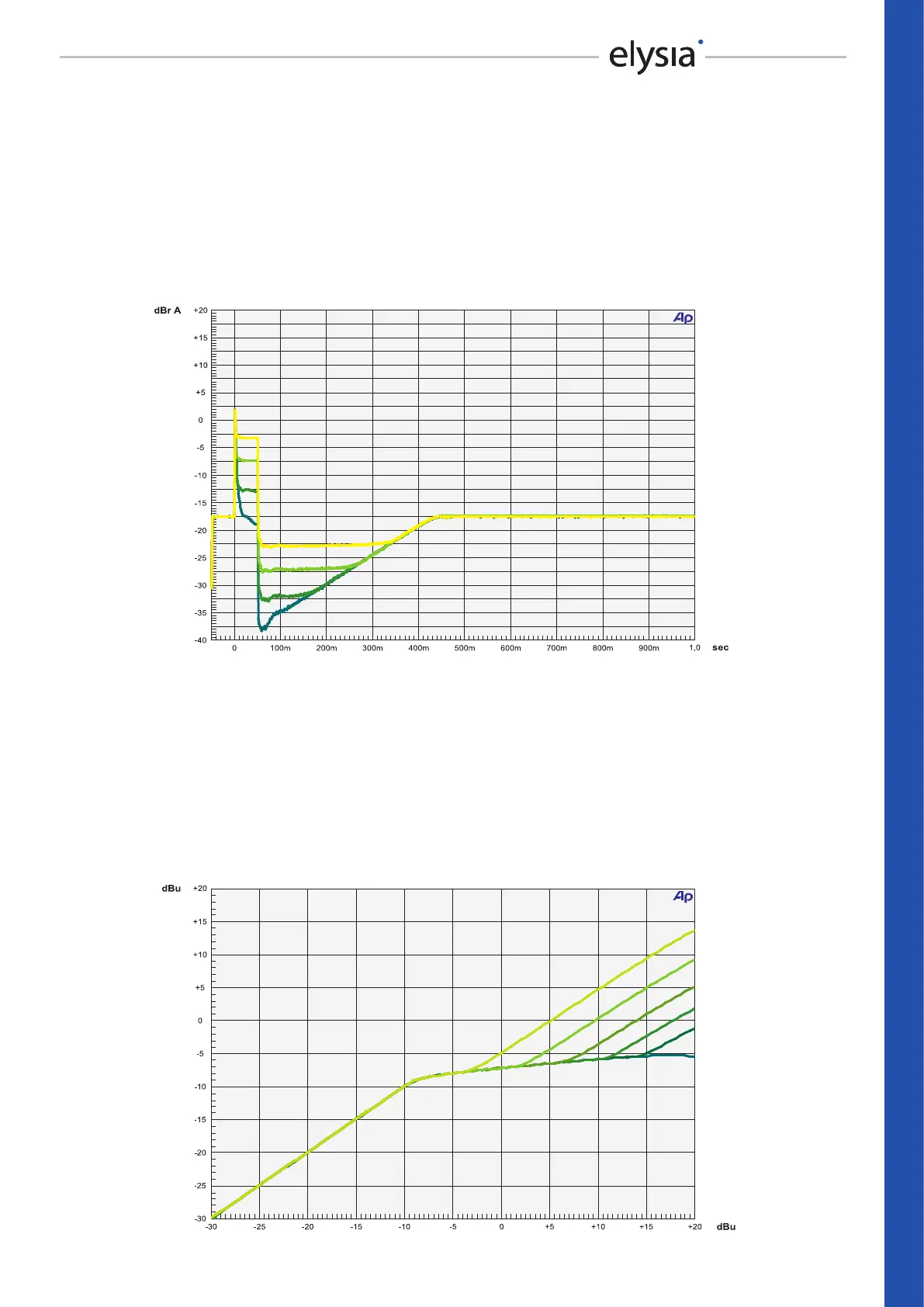
GR Limit Envelope
Here, a burst signal is used to demonstrate the eect of the Gain Reduction Limiter. While the
lowest curve represents the maximum amount of gain reduction in this example, the other curves
show the reduction that is inuenced by dierent settings of the now activated limiter. The eect
of this function can also be observed with a look at the gain reduction LED meter: The displayed
value never exceeds the limit which is set with the GR Limit controller – no matter, how high the
input level might become.
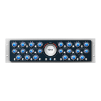
GR Limit Characteristic
Finally, a sine wave which increases in level is used in another angle of specifying the eect of the
Gain Reduction Limiter. The lowest curve shows a compressed signal with a high ratio and without
the limiter. The other curves reveal how the output level starts to rise again after the compression
phase, because the maximum amount of gain reduction which is set with the GR Limit controller
has already been utilized completely. This eect can be used to achieve compression within a se-
lective range of level exclusively, whereby loud signals can still keep their original dynamics.
REFERENCE – GR Limit Envelope & Characteristic