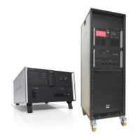
EM TEST coupling NX
Manual of operation V 1.03 3 / 53
Contents
1. General ........................................................................................................................................................... 5
1.1. Purpose ................................................................................................................................................. 5
1.2. Warranty Terms..................................................................................................................................... 5
1.3. Product return procedure ...................................................................................................................... 6
1.4. Recycling and Disposal ......................................................................................................................... 6
1.4.1. RoHS directive 2011/65/EU (RoHS 2) .................................................................................................. 6
1.4.2. WEEE directive 2012/19/EU ................................................................................................................. 6
1.4.3. Dismantling information ......................................................................................................................... 6
1.4.4. Parts which can be recycled ................................................................................................................. 6
10.5 Parts which cannot be recycled ............................................................................................................ 6
2. Safety information ......................................................................................................................................... 7
2.1. Intended use.......................................................................................................................................... 7
2.2. Responsibility of the operator ................................................................................................................ 7
2.3. General hazard...................................................................................................................................... 7
2.4. Qualification of personnel ...................................................................................................................... 8
2.5. Safety label on the device ..................................................................................................................... 8
2.6. Prohibition of unauthorized conversions and modifications .................................................................. 8
3. Installation put in service ............................................................................................................................. 9
3.1. Safety instructions for installation and initial installation ....................................................................... 9
3.1.1. Qualifications of the staff ....................................................................................................................... 9
3.1.2. Installation ............................................................................................................................................. 9
3.2. Installation of the coupling NX series .................................................................................................. 10
3.2.1. Unpacking ........................................................................................................................................... 10
3.2.2. Grounding and power connection ....................................................................................................... 11
3.2.3. Mains Switch and fuse ........................................................................................................................ 12
3.2.4. Connecting the compact NX5 system to the ground reference .......................................................... 12
3.2.5. Connecting System coupling NX with compact NX5 generator .......................................................... 13
4. List of coupling networks ........................................................................................................................... 14
4.1. Coupling networks for IEC pulses ....................................................................................................... 14
4.2. Special Coupling networks for IEC pulses .......................................................................................... 14
5. Operating Functions ................................................................................................................................... 15
5.1. coupling NX5 bs-3-480-16 / 32 ........................................................................................................... 15
5.1.1. Front view coupling NX5 bs-3-480-16 / 32 .......................................................................................... 15
5.1.2. Rear side coupling NX5 bs-3-480-16 / 32 ........................................................................................... 16
5.2. Rack with built in coupling NX5-bs-480-125 ....................................................................................... 17
5.2.1. Front and rear view coupling NX5-bs-480-125 ................................................................................... 17
5.2.2. Connecting plate coupling NX5 bs-3-480-125 Rack ........................................................................... 18
5.3. Rack with built in Coupling NX5-bs-3-690-200.3 ................................................................................ 19
5.3.1. Front and rear view coupling NX5-bs-3-690-200.3 ............................................................................. 19
5.3.2. Front and rear view coupling NX5 bs-3-690-200.x ............................................................................. 20
5.3.3. Connecting plate coupling NX5 bs-3-690-200.3 Rack ........................................................................ 21
5.3.4. Current Range selector NX5 bs-3-690-200 ........................................................................................ 23
6. General ......................................................................................................................................................... 24
6.1. Coupling modes .................................................................................................................................. 24
6.2. Coupling to Signal Lines ..................................................................................................................... 24
6.3. Surge coupling decoupling networks rated up to 200 A ..................................................................... 25

 Loading...