Connecting Multiple Expansion Shelves
NOTE: This guide describes the installation of new systems comprised of all ES
SAS shelf models. Configurations including a mix of ES, ES SATA, and ES
SAS shelves are subject to additional configuration constraints. The instructions
for mixing shelf types are in the ES30 Hardware Guide.
EXPANSION SHELF CABLING
The system supports any combination of 30 and 45 TB ES30 SAS shelves up
to a maximum of 32 shelves with 1440 TB of raw storage. Multiple expansion
shelves are connected together and to the controller with qualified SAS
cables. Save extra SAS cables for future use. See Figure 4 for the recom-
mended cabling and component placement of a system. The cables provided
support the DD4500 with Extended Retention Software and ES30s in the rack
positions as shown.
Note: Cables have an HD-mini-SAS end that connects to the controller and a
mini-SAS end that connects to the shelves.
ES Expansion Shelves
4Use a SAS cable with mini-SAS connectors for any ES30 SAS connection.
4Cables should be dressed to the side of the rack and supported with
Velcro straps to allow for easy removal of a shelf controller or power
supply.
4In the DD4500 with Extended Retention Software the strings are not
contiguous. The order of shelf addition is designed for easy expansion
from a standard DD4500 system and to (nearly) fill a rack before adding
the next rack. The gaps in the racks are positioned to create a standard
expansion rack that is just re-cabled based on its position.
HOT ADDITION OF EXPANSION SHELVES
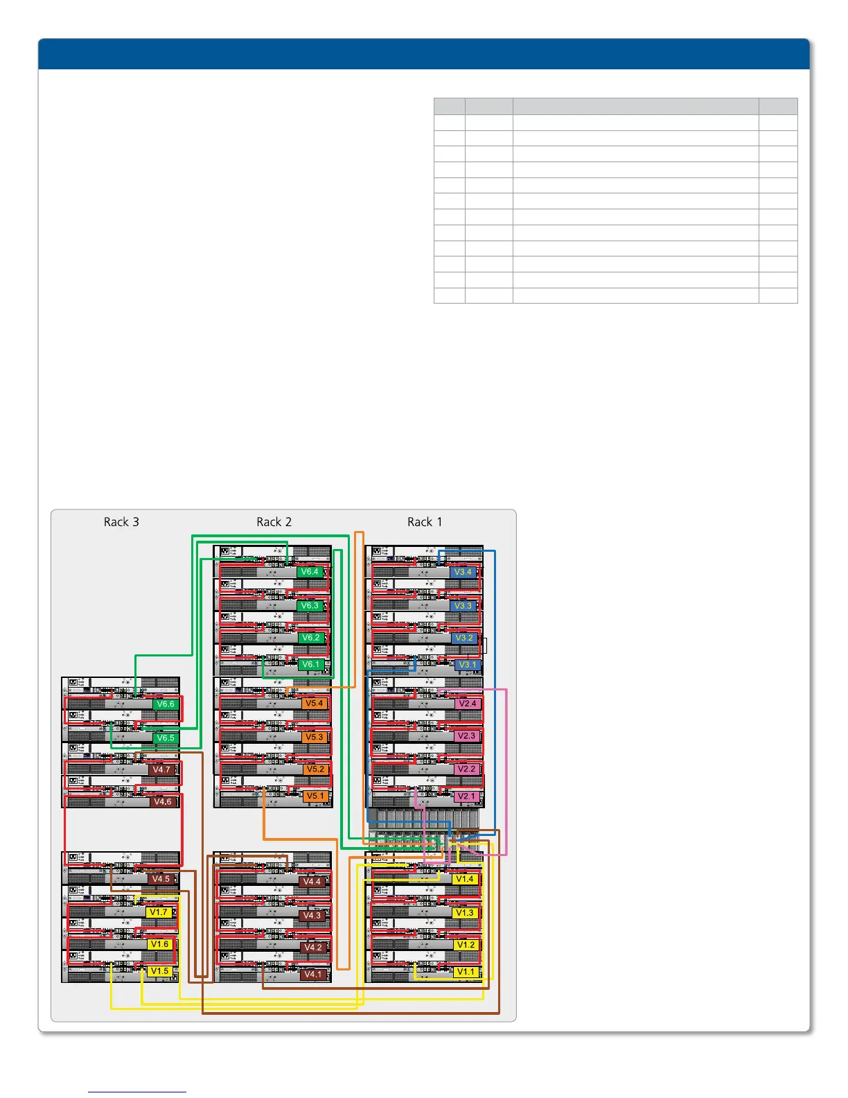
NOTE: In Figure the shelves are labeled VN.M. VN refers to string “N” and
the “M” is the number of the shelf in the string. The cabling and racking are
designed so that shelves are added from the bottom up in a rack. Therefore,
shelves are added V., V., V., V., V., V., and so on. Add shelves in
order, one at a time. Refer first to the Cabling Instructions table for adding
or moving HBA-to-shelf cables. Then add the necessary shelf-to-shelf cables
between shelves in a string as shown in Figure 4. Note that the added shelf will
become the highest number shelf in its string, requiring
one HBA-to-shelf cable to be moved to connect to its
controller A or controller B HOST port.
Cabling between adjacent shelves in a string is done
with the 1M SAS cables that are delivered with the
shelves. Cable from the B Controller EXPANSION
port of lower shelf to the B controller HOST port of
the next higher shelf. Then cable from the A Controller
HOST port of lower shelf to the A controller
EXPANSION port of the next higher shelf.
When adding shelves to an existing string, move the
cable from the B controller HOST port to the new
shelf and then add the shelf-to-shelf 1M cables. 2M,
3M, and 5M cables are supplied to best match the
routing requirement. Loop any excess and use the
Velcro straps to attach to a convenient place in the rack.
“3” is the top HBA port and “0” is the bottom.
Shelves are added to rack1 from bottom to top in the
positions shown. Then rack2 is filled from bottom to
top, leaving the gap. The third rack is added in order.
Because strings are split between racks, the cables
connecting one shelf to another are longer.
EMC DATA DOMAIN DD4500 WITH EXTENDED RETENTION SOFTWARE INSTALLATION AND SETUP GUIDE
|
SIDE 1
FIGURE : RECOMMENDED ES CABLING DIAGRAM (matches factory configuration)
CABLING INSTRUCTIONS
String IO port Shelf port Length*
1 A7 Port 1
B controller HOST port of shelf V1.1
2M
1 A8 Port 0
A controller HOST port of the highest number shelf in V1
2M/3M
2 A7 Port 0
B controller HOST port of shelf V2.1
2M
2 A8 Port 1
A controller HOST port of the highest number shelf in V2
2M/5M
3 A7 Port 3
B controller HOST port of shelf V3.1
2M
3 A8 Port 2
A controller HOST port of the highest number shelf in V3
2M/5M
4 A7 Port 2
B controller HOST port of shelf V4.1
3M
4 A8 Port 3
A controller HOST port of the highest number shelf in V4
3M/5M
5 A6 Port 0
B controller HOST port of shelf V5.1
3M
5 A5 Port 1
A controller HOST port of the highest number shelf in V5
3M/5M
6 A5 Port 0
B controller HOST port of shelf V6.1
3M
6 A6 Port 1
A controller HOST port of the highest number shelf in V6
3M/5M
* When two lengths are shown, the longer is used when a string is split between racks.
When a string is split between racks the shelf to shelf cable lengths are: 2M for V2, V3,
V4, V5, or V6. Cable lengths shown are designed for EMC racks. Other racks may require
longer cables.
Power-Up and Final Configuration
Follow the steps described in Chapter 4, Post
Installation Tasks, of the ES30 Expansion Shelf Hardware
Guide to complete hot addition of expansion shelves to
an existing system.
 Loading...