Step 6: External network cables
77
Connect Cables for a Fabric-connected VG2
EMC CONFIDENTIAL
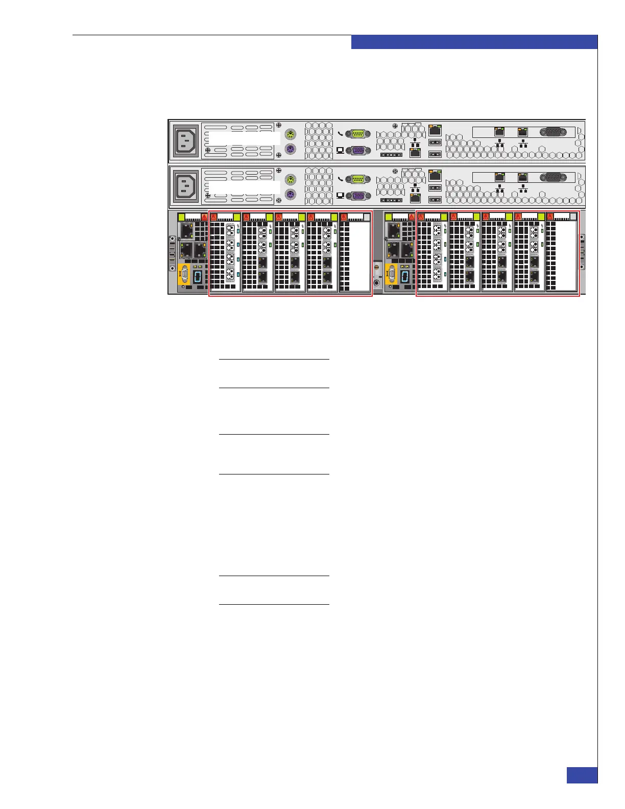
3. Connect the copper Ethernet cables from the ports on the I/O modules
(Figure 45) to the customer’s public Ethernet network. Appendix H, “Setup
Worksheets,” provides information.
Figure 45 VG2 public network ports
Note: For successful blade failover, you must establish identical network connections for
the primary and standby blades.
4. Connect up to two optical Ethernet cables from ports on the I/O modules
(Figure 45 on page 77) to the customer’s Gigabit Ethernet network.
Note: If the link light is off when the optical cables are connected, try swapping the receive
and transmit connections. Some combinations of patch panels and multiple cables between
the blade and the Ethernet switch can result in the connections being reversed.
5. If you are using the VNX VG2 gateway with a VNX array, ensure the Control
Station external network is configured to have a network path to the VNX SPs.
The network connectivity will be verified when you configure the Control
Station.
Do not connect the VNX SPs to the management modules that connect the blades
to the Control Station.
Note: The Control Station does not connect to a Symmetrix array through the Ethernet
network. All Symmetrix management is done outside the Control Station.
6. Go to Chapter 8, “Configure the boot array.”
Serial
console
MGMT
CS
B
MODEM plug
VGA socket
A
0
123
0
123
0
12 3
0
1 23
0
1 23
0
1 23
0
1 23
0
1
23
0
12 3
0
12 3
Serial
console
MGMT
CS
B
MODEM plug
VGA socket
A
Control Station 1
Blade 3 I/O modules and ports
Control Station 0
CNS-001681
Blade 2 I/O modules and ports
 Loading...