38 VNX5500 Hardware Information Guide
System component description
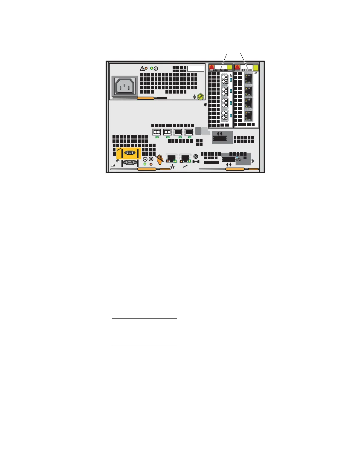
Figure 29 Example of SP with a Fibre Channel (FC) I/O module and an iSCSI I/O module
For a full description of the I/O module types used in the SP, go to the “I/O modules”
section on page 47.
Control Station rear view
On the rear, viewing from left to right, the Block and File (Unified) VNX5500 platform
Control Station includes the following hardware components:
◆ AC (power in) recessed connector (plug)
◆ Two PS/2 connectors (keyboard and mouse)—not used
◆ One (DB-9 plug) serial modem connector
◆ One (DB-15) video (VGA socket) connector—not used
◆ Four (RJ-45) NIC (labeled A, CS, B, and MGMT) connectors
Note: The RJ-45 NICs (labeled A and CS) are integrated into the rear of the Control
Station while the RJ-45 NICs (labeled B and MGMT) are on a PCI-E card in the
expansion slot on the rear of the Control Station.
◆ One (DB-9 plug) serial console (RS-232/EIA-232) connector
◆ Two USB 2.0 connectors—not used
◆ POST diagnostic LEDs
◆ Two CAT-5E/6 panel-mount Ethernet cable extensions
X4
2
3
4
5
6Gb
SAS
8Gb
bre
1
0 X4
6Gb SAS
SP I/O Module Slots
0123
PART NUMBER
REV A09 A
0
123
PART NUMBER
REV A09 A
VNX-000569


 To Next Page