Do you have a question about the Emerson 543-0012-00 and is the answer not in the manual?
Describes the function of the POWER, ALERT, and TRIP LEDs.
Details product applications, benefits, and technical specifications.
Guides the physical mounting of the Comfort Alert module.
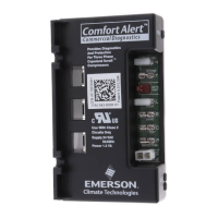
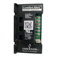
Shows dimensions and diagnostic keys for specific Comfort Alert models.
Shows dimensions and diagnostic keys for specific Comfort Alert models.
Explains how compressor wires are routed through the module.
Details the connection requirements for the 24VAC power supply.
Provides a wiring diagram for AC systems (543-0010-00, 943-0010-00).
Explains how the thermostat demand signal connects to the module.
Provides a wiring diagram for AC systems (543-0010-01, 943-0010-01).
Provides wiring diagrams for heat pump system configurations.
Provides a wiring diagram for AC/Heat Pump systems (543-0032-00).
Provides wiring diagrams for two-stage AC/Heat Pump systems.
Explains the use of the L terminal for thermostat communication.
Details wiring for two-stage cooling applications.
Describes the connection to the compressor's second-stage solenoid.
Explains how to understand the LED flash codes for diagnostics.
Outlines functional tests to verify correct installation.
Discusses how system configuration affects alert codes.
Details manual and automatic methods for resetting alert codes.
Lists LED status, descriptions, and troubleshooting steps for codes.
Continues LED troubleshooting information and lists common issues.
Details indications and actions for miswired Comfort Alert modules.
| Brand | Emerson |
|---|---|
| Model | 543-0012-00 |
| Category | Diagnostic Equipment |
| Language | English |