Do you have a question about the Emerson Comfort Alert 543-0071-00 and is the answer not in the manual?
| Brand | Emerson |
|---|---|
| Model | Comfort Alert 543-0071-00 |
| Category | Diagnostic Equipment |
| Language | English |
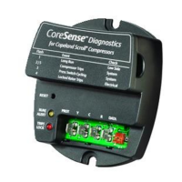
Overview of the Comfort Alert module, highlighting faster service and improved accuracy benefits.
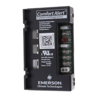
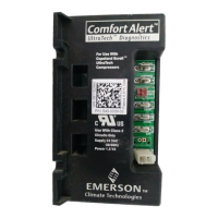
Explanation of the POWER, ALERT, and TRIP LEDs, including their status and meaning.
Details on operating temperature, power supply, requirements, and UL restrictions.
Physical dimensions for two-stage and single-stage models, and layout overview.
Guidance on module mounting, screw torque, and related hardware.
Instructions for routing compressor wires through the module's designated holes.
Specifies the requirement for a constant 24VAC power supply for the module.
Describes how to connect the thermostat demand signal (Y) to the module.
Details connecting the Comfort Alert module to a system controller and PROT terminal monitoring.
Explains wiring for two-stage thermostat applications and Y2 input for cooling.
Describes using the L terminal to communicate Alert codes to compatible thermostats.
Details connecting to the Copeland two-stage second stage compressor solenoid.
Explains the PROT terminal's role in compressor protection and safety.
States that Comfort Alert is not a substitute for safety cutout devices.
Guides on understanding abnormal system conditions via LED indicators and flash codes.
Procedures for performing functional tests to ensure correct module installation.
Methods for manually and automatically resetting alert codes on the Comfort Alert module.