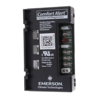
The Comfort Alert® Diagnostics module is an innovative device designed to troubleshoot failures in heat pump and air conditioning systems. It simplifies service and improves accuracy by monitoring and analyzing data from Copeland Scroll® compressors and thermostat demand signals. The module installs easily in the outdoor unit's electrical box, near the compressor contactor, and operates without additional sensors.
Function Description:
The Comfort Alert module detects the cause of electrical and system-related failures. It communicates abnormal conditions through a flashing yellow ALERT LED, which displays unique flash codes. These codes guide service technicians to the root cause of a problem, speeding up diagnostics. The module is compatible with Emerson branded thermostats (1F9X and 1F8X families) that offer an "L" terminal connection for diagnostic communication. Certain "CA" model thermostats can display Comfort Alert codes on their screen and actively protect the compressor by shutting it off if a potentially harmful fault code is detected.
The device is optimized for various air conditioning applications, including cooling-only, heat pump, two-stage compressors, and commercial three-phase systems. This manual specifically covers single-phase applications. It's important to note that the Comfort Alert module is a monitoring device and does not provide safety protection or control other devices.
Important Technical Specifications:
Part Numbers and Applications:
- 543-0010-00 (Service Number: 943-0010-00) / 543-0010-01 (Service Number: 943-0010-01): A/C: Single Stage with Copeland Scroll®
- 543-0012-00 (Service Number: 943-0012-00): Heat Pump: Single Stage with Copeland Scroll®
- 543-0032-00: A/C and Heat Pump: Single Stage with Copeland Scroll®
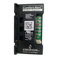
- 543-0033-02 (Service Number: 943-0033-00): A/C and Heat Pump: Two Stage with Copeland Scroll® UltraTech
General Product Specifications:
- Operating Temperature: -40° to 150° F (-40° to 65° C)
- Storage Temperature: -40° to 175° F (-40° to 80° C)
- UL Restrictions: Use only with Class 2 circuits
Power Supply Range and Requirement:
- For 543-0010-00, 543-0010-01, 543-0012-00:
- Supply: 19-28VAC, 48-62 Hz
- Power Requirement: 0.5 VA nominal
- For 543-0032-00, 543-0033-02:
- Supply: 18-30VAC, 48-62 Hz
- Power Requirement: 1.5 VA nominal (without solenoid on); 7.0 VA nominal (with solenoid on for 543-0033-02)
Physical Dimensions:
- For 543-0010-00, 943-0010-00, 543-0012-00, 943-0012-00:
- A: 1.81 in (46 mm)
- B: 2.44 in (62 mm)
- C: 1.43 in (36 mm)
- D: 3.15 in (80 mm)
- E: 2.44 in (62 mm)
- For 543-0010-01, 943-0010-01:
- A: 1.81 in (46 mm)
- B: 2.44 in (62 mm)
- C: 1.43 in (36 mm)
- D: 3.15 in (80 mm)
- E: 2.44 in (62 mm)
- For 543-0032-00, 543-0033-00, 543-0033-02:
- A: 1.85 in (47 mm)
- B: 2.44 in (62 mm)
- C: 1.46 in (37 mm)
- D: 4.40 in (112 mm)
- E: 2.44 in (62 mm)
Usage Features:
LED Indicators:
- POWER LED (Green): Indicates voltage is present at the module's power connection.
- ALERT LED (Yellow): Communicates abnormal system conditions via flash codes. A flash code is a sequence of consecutive flashes followed by a pause, repeating the process. The number of flashes corresponds to a specific condition.
- TRIP LED (Red): Indicates a demand signal from the thermostat but no current detected at the compressor. This typically suggests an open compressor protector or missing supply power.
Wiring:
- Compressor Wire Routing: The compressor's run (R), common (C), and start (S) wires are routed through designated holes in the Comfort Alert module. The common (C) wire is not strictly necessary for module operation.
- 24VAC Power Wiring (except 543-0010-01, 943-0010-01): Requires a constant nominal 24VAC supply directly from the indoor unit or thermostat to the module's R and C terminals. Powering from a defrost board or other control board's C terminal may cause nuisance alerts. If constant 24VAC (R wire) is unavailable in the outdoor unit, a spare wire from the thermostat cable can be used, connecting its other end to R at the indoor unit or thermostat.
- 24VAC Power Wiring (for 543-0010-01, 943-0010-01): 24VAC power wiring is not required as these models are powered by the demand (Y terminal).
- Thermostat Demand Wiring: The Y terminal on the module should be connected to the compressor contactor coil. When the coil is energized, Y should receive 24VAC; otherwise, it should be less than 0.5VAC. Proper phasing of R and C relative to Y should be verified by measuring 24VAC across Y and C when demand is present (except for 543-0010-01, 943-0010-01).
- L Terminal Wiring (for 543-0032-00, 543-0033-02, 943-0033-00): The L connection communicates Alert codes to compatible White-Rodgers® thermostats. Connecting the thermostat's L terminal directly to the Comfort Alert L terminal enables the thermostat to flash the Alert icon and, in advanced settings, lock out the compressor for certain critical Alert codes.
- Thermostat Second Stage Cooling Wiring (for 543-0033-02, 943-0033-00): Designed for two-stage Copeland Scroll® UltraTech™ compressors, this model requires a two-stage thermostat. The Y2 thermostat wire from the outdoor unit connects to the Y2 input on Comfort Alert.
- DC SOL Connection (for 543-0033-02, 943-0033-00): A two-pin DC SOL connector provides connection to the internal Copeland Scroll UltraTech second-stage compressor solenoid. This 24VDC solenoid requires a specific DC voltage (4-18VDC) provided by Comfort Alert, not direct 24VAC. Comfort Alert intelligently adjusts the DC voltage to minimize power consumption.
Installation:
- Requires four #8 or (#10 for part # -0032 and -0033) self-drilling or sheet metal screws (at least 1½" long).
- Maximum screw torque: 20 in.-lbs.
- Should be mounted near the compressor contactor for easier wire routing.
- Mount in any orientation, but ensure all LEDs are visible. For ease of reading, orient the module so the green POWER LED is at the top.
Maintenance Features:
Interpreting Diagnostic LEDs:
- When an abnormal condition occurs, the module displays the appropriate ALERT and/or TRIP LED. The yellow ALERT LED flashes a code, pauses, and repeats. The number of flashes identifies the Flash Code.
- The last ALERT Flash Code before shutdown is displayed for one minute upon module power-up.
Installation Check:
- Functional Test 1 (Trip LED): Disconnect compressor power, force a cooling call. The red Trip LED should illuminate, indicating a compressor trip, as long as 24VAC is measured at the Y terminal. If not, check wiring (Table 1).
- Functional Test 2 (Alert LED - for all models except 543-0010-01, 943-0010-01): Disconnect compressor power and 24VAC from Comfort Alert. Remove the wire from the Y terminal, reapply 24VAC to Comfort Alert and compressor. Force a cooling call. The yellow Alert LED should flash Code 8 (Welded Contactor). Disconnect power again, reattach the Y wire, reapply power. The yellow Alert LED will flash Code 8 for 1 minute then turn off. If not, check wiring (Table 1).
Resetting Alert Codes:
- Manual Reset: Cycle power to Comfort Alert off and on.
- Automatic Reset: The module continues monitoring after an alert. If conditions return to normal, the alert code turns off automatically.
- After a power-on reset, the prior alert code flashes for 60 seconds.
- Note: For 543-0010-01 and 943-0010-01, auto-reset is the only available option.
Troubleshooting Tables:
- LED Troubleshooting Information (Pages 11-12): Provides detailed descriptions and troubleshooting steps for each Flash Code (1-9) and for the POWER and TRIP LEDs.
- Miswired Module Indication (Page 13): Describes LED behavior when the module is miswired and provides recommended troubleshooting actions. It emphasizes using the correct Comfort Alert model for the application to ensure accurate fault detection.
Safety Warning:
- Hazardous voltage is present inside the air conditioning system. Disconnect power before installing or servicing the module. Installation and service must only be performed by qualified personnel.