Compressor Wire Routing (Figure 5)
The scroll compressor’s run (R), common (C) and start (S) wires are routed through the
holes in Comfort Alert marked “R,” “C” and “S.” The common (C) wire need not be routed
through the module for it to operate properly.
24VAC Power Wiring
(except 543-0010-01, 943-0010-01)
Comfort Alert requires a constant nominal 24VAC
power supply. The wiring to the module’s R and
C terminals must be directly from the indoor unit
or thermostat. The module cannot be powered by
the C terminal on a defrost board or other
control board without experiencing nuisance
alerts. Refer to Figures 6 thru 10.
When constant 24VAC (R wire) is not present in
the outdoor unit, use one of the spare wires in the
thermostat cable to bring power to the module.
Connect the other end of the spare wire to R at
the indoor unit or thermostat. Refer to wiring
schematic in Figures 6 thru 10.
Figure 5
Copeland Scroll®
Compressor
4
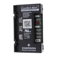
Part Numbers: 543-0032-00, 943-0033-00, 543-0033-02
A. 1.85 in (47 mm) D. 4.40 in (112mm)
B. 2.44 in (62 mm) E. 2.44 in (62 mm)
C. 1.46 in (37 mm)
Figure 4
 Loading...