2
Application, Benefits And Product Specifications
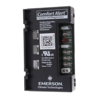
Part Number:
(Service Number)
543-0010-00
543-0010-01
(943-0010-00)
(943-0010-01)
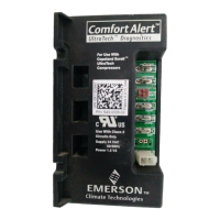
543-0012-00
(943-0012-00)
543-0032-00
543-0033-02
(943-0033-00)
Application
A/C: Single Stage
with Copeland Scroll
®
Heat Pump: Single
Stage with Copeland
Scroll
®
A/C and Heat Pump:
Single Stage with
Copeland Scroll
®
A/C and Heat Pump:
Two Stage with
Copeland Scroll
®
UltraTech
Benefits
Diagnostic Alert
Codes
ü ü ü ü
Trip Indicator
ü ü ü ü
Data Port
ü ü ü ü
L-Terminal
Communication
ü ü
2 Stage Solenoid
Control
ü
Product Specifications
Operating
Temperature
-40° to 150° F
(-40° to 65° C)
-40° to 150° F
(-40° to 65° C)
-40° to 150° F
(-40° to 65° C)
-40° to 150° F
(-40° to 65° C)
Storage
Temperature
-40° to 175° F
(-40° to 80° C)
-40° to 175° F
(-40° to 80° C)
-40° to 175° F
(-40° to 80° C)
-40° to 175° F
(-40° to 80° C)
Power Supply
Range
19-28VAC,
48-62 Hz
19-28VAC,
48-62 Hz
18-30VAC,
48-62 Hz
18-30VAC,
48-62 Hz
Power
Requirement
0.5 VA nominal 0.5 VA nominal 1.5 VA nominal
1.5VA nominal
(without solenoid on)
7.0VA nominal
(with solenoid on)
UL Restrictions
Use only with
Class 2 circuits
Use only with
Class 2 circuits
Use only with
Class 2 circuits
Use only with
Class 2 circuits
WARNING
Hazardous voltage inside air conditioning system. Discon-
nect power before installing or servicing module. Module
must be installed and serviced only by qualified personnel.
Hardware Installation
Four #8 or (#10 for part # -0032 and -0033) self drilling or sheet metal screws, at least
½” length, are required for installation of Comfort Alert. The maximum screw torque is
20 in.-lbs. Locate Comfort Alert near the compressor contactor (wire routing for
compressor run, common and start wires will be easier in this position). Mount Comfort
Alert so all LEDs are visible from a comfortable viewing position. The module will
operate in any mounting orientation. For ease of reading labels, the module should be
oriented so that the green POWER LED is at the top. See Figures 2, 3 and 4.
 Loading...