1592023020 XM660K_XM669K GB r1.0 07.01.2013.doc XM660K - XM669K 6/8
13. RS485 SERIAL LINE
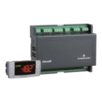
XM660K/XM669K is provided of a direct RS485 connection that allow the unit, to be linked to a network
line ModBUS-RTU compatible with all dIXEL monitoring system.
14. USE OF THE PROGRAMMING “HOT KEY“
The XM units can UPLOAD or DOWNLOAD the parameter list from its own E2 internal memory to the
“Hot Key” and vice-versa through a TTL connector.
14.1 DOWNLOAD (FROM THE “HOT KEY” TO THE INSTRUMENT)
1. Turn OFF the instrument by means of the ON/OFF key ,insert the “Hot Key” and then turn the
unit ON.
2. Automatically the parameter list of the “Hot Key” is downloaded into the controller memory, the
“doL” message is blinking. After 10 seconds the instrument will restart working with the new
parameters. At the end of the data transfer phase the instrument displays the following
messages: “end“ for right programming. The instrument starts regularly with the new
programming. “err” for failed programming. In this case turn the unit off and then on if you want
to restart the download again or remove the “Hot key” to abort the operation.
14.2 UPLOAD (FROM THE INSTRUMENT TO THE “HOT KEY”)
1. When the XM unit is ON, insert the “Hot key” and push è key; the "uPL" message appears.
2. The UPLOAD begins; the “uPL” message is blinking.
3. Remove the “Hot Key”.
At the end of the data transfer phase the instrument displays the following messages:
“end “ for right programming.
“err” for failed programming. In this case push “SET” key if you want to restart the programming
again or remove the not programmed “Hot key”.
15. ALARM SIGNALS
Compressor output acc. to par.
Compressor output acc. to par.
Maximum temperature alarm
Minimum temperature alarm
Stop due to regulation pauses
Std parameters)
Lock due to pressure switch
Compressor and fans restarts according to rrd and
odc
Serious external alarm (i#
Minimum operating pressure reached
Maximum operating pressure reached
15.1 “EE” ALARM
The dIXEL instruments are provided with an internal check for the data integrity. Alarm “EE” flashes
when a failure in the memory data occurs. In such cases the alarm output is enabled.
15.2 ALARM RECOVERY
Probe alarms : “P1” (probe1 faulty), “P2”, “P3”, “P4”, “P5”, “P6”; they automatically stop 10s after the
probe restarts normal operation. Check connections before replacing the probe. Temperature alarms
“HA”, “LA”, “HAd”, “LAd”, “HAF”, “LAF” automatically stop as soon as the thermostat temperature
returns to normal values or when the defrost starts. External alarms “EAL”, “BAL” stop as soon as the
external digital input is disabled.
16. TECHNICAL DATA
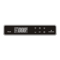
CX660 keyboard
Housing: self extinguishing ABS.
Case: CX660 facia 35x77 mm; depth 18mm
Mounting: panel mounting in a 29x71 mm panel cut-out
Protection: IP20; Frontal protection: IP65
Power supply: from XM600K power module
Display: 3 digits, red LED, 14,2 mm high;
Optional output: buzzer
Power modules
Case: 8 DIN
Connections: Screw terminal block
≤
1,6 mm
2
heat-resistant wiring and 5.0mm Faston
Power supply: depending on the model 12Vac – 24Vac - 110Vac
±
10% - 230Vac
±
10% or
90÷230Vac with switching power supply.
Power absorption: 9VA max.
Inputs: up to 6 NTC/PTC/Pt1000 probes
Digital inputs: 2 free of voltage
Relay outputs: Total current on loads MAX. 16A
Solenoid Valve: relay SPST 8 A, 250Vac
defrost: relay SPST 16 A, 250Vac
fan: relay SPST 8 A, 250Vac
light: relay SPST 16 A, 250Vac
Valve output: a.c. output up to 30W (Only XM669K)
Optional output (AnOUT) DEPENDING ON THE MODELS:
• PWM / Open Collector outputs: PWM or 12Vdc max 40mA
• Analog output: 4÷20mA or 0÷10V
Serial output: RS485 with ModBUS - RTU and LAN
Data storing: on the non-volatile memory (EEPROM).
Kind of action: 1B. Pollution grade: normal Software class: A. Operating temperature: 0÷60 °C.
Storage temperature: -25÷60 °C. Relative humidity: 20
÷
85% (no condensing).
Measuring and regulation range:
NTC probe: -40÷110°C (-58÷230°F).
PTC probe: -50÷150°C (-67 ÷ 302°F)
Pt1000 probe: -100 ÷ 100°C (-148 ÷ 212°F)
Resolution: 0,1 °C or 1°C or 1 °F (selectable). Accuracy (ambient temp. 25°C): ±0,5 °C ±1 digit
17. CONNECTIONS
17.1 XM660K – ALL POWER SUPPLY
17.2 XM669K – 230/110VAC VALVE COIL
NOTE: the jumper indicated as JMP is inside the case of the controller. This jumper
has to be closed only in case of driving 24Vac valve.
17.3 XM669K – 24VAC VALVE COIL
18. DEFAULT SETTING VALUES
Lab Val Menù Description Range
SEt
2.0 - - - Set point LS - US
Regulation
Hy
2.0 Pr1 Differential [0.1°C ÷ 25.5°C] [1°F ÷ 45°F]
Int
150 Pr1
Integral time for room
temperature regulation
0 ÷ 255 s
CrE
n Pr1
Continuous regulation
activation
n(0) – Y(1)
LS
-30 Pr2 Minimum set point [-55.0°C ÷ SET] [-67°F ÷ SET]
US
20 Pr2 Maximum set point
[SET ÷ 150.0°C] [SET ÷
302°F]
odS
0 Pr1
Outputs activation delay at start
up
0 ÷ 255 (min.)
AC
0 Pr1 Anti-short cycle delay 0 ÷ 60 (min.)
CCt
0.0 Pr2 Continous cycle duration 0 ÷ 24.0(144) (hour.10min)

 Loading...
